-
Issue Feedback January In the January 2024 issue, the first paragraph of “The World Above 50 MHz” column contains an incorrect name and call sign. The second sentence and the beginning of the third sentence should read, “The W8S team on Swains Island made 6-meter Earth-Moon-Earth (EME) contacts with KJ9I and Gary, K9RX (EM85), who was the second ham to work W8S, followed by NØTB. Gary applauded…” This has since been corrected in the digital edition. January In the January 2024 issue of QST, transmit-receive turnaround times with AMS on the radio disabled were left of of Table 1 in the Yaesu FTM-500DR review in Product Review. These have since been added to the digital edition. Janaury In the January 2024 issue of QST, "FT8 Visualized" contains an error. The second and third sentences in the first paragraph under the "Final FT8 Format and More Resources" subhead should read, "These are assembled in groups of three and converted to Gray code to get 5 symbols or transmitted tones. Add the three Costas arrays of seven symbols each (21 symbols in total) to determine that an FT8 message is 79 symbols, or the equivalent of 237 binary bits." This has since been corrected in the digital edition. February In "The Un-Unly Balun Form" by John Portune, W6NBC, and Jim Bailey, W6OEK, in the February 2024 issue, it was incorrectly stated that an ugly balun can be used to cover several higher frequency bands than the one for which is was designed. Due to self-resonance of the balun windings, the frequency range is limited to one or two higher frequency bands at most. Additionally, 3D-printer files that will assist with the build are now accessible on QST in Depth (www.arrl.org/qst-in-depth). February In the February 2024 issue of QST, "How's DX?" contains an error. The first paragraph states that Alejandro Selkirk Island had never been activated before, but the CB0Z operation was conducted there in 2020. This has since been corrected in the digital edition. -
Issue Feedback January In the January 2023 issue of QST, Figure 2 in "Antenna Switch for Three Remote Operating Locations" in the Hints & Hacks" column contains two incorrect connections. The Relay 2 connection to the yellow wire should be made to the green wire, and the junction of the S2 and LED4 connection to the yellow wire should also be made to the green wire. A Corrected schematic has been added to the QST in Depth web page at www.arrl.org/qst-in-depth. February In the February 2023 "Product Review," two errors were made that have since been corrected in the digital edition. First, the placement of Figures B and C should be reversed. Please note that this referes to the images only; the captions are in the correct places. Second, in the caption for Figure C, the second sentence should read, "Third-order products are -28 DbPEP, the fifth-order products are -39 dBPEP." March In the March 2023 issue of QST, an error was made that has since been corrected in the digital edition. In "W9BSP: Remembering a Historic CW Mentor, 100 Years Lager" by Leanna Figlewski, KC1RMP, Don Mix's call sign was incorrectly listed as W1TC. His correct call sign was W1TS. May In the May 2023 issue of QST, an error was made that has since been corrected in the digital edition. In "FCC Exposure Rules Soon to Affect Every US Radio Amateur" by Gregory Lapin, N9GL, the dimensions assiciated with the two triamgles in t Figure 2 were unclear. The corrected figure is shown in the QST InDepth files. September The September 2023 "Convention and Hamfest Calendar" has an incorrect date of September 9 for the Midwest Superfest in Chillicothe, Illinois. The actual dates for the event are Septemer 16-17, 2023. November In the November 2023 issue of QST, an error was made that has since been corrected in the digital edition. In "The LPi Antenna" by Jacek Pawlowski, SP3L, the interconnections of the two inductors in Figure 2 should be connected as shown here. November In the November 2023 issue, Figure 3 in "A Simple, Portable Satellite Tracker" by Ray Crafton, KN2K, contained two errors. Both instances of LM2569 should be LM2596. This has since been corrected in the digital edition. November IIn the November 2023 issue of QST, an error was made that has since been corrected in the digital edition. In the “Ask Dave” column, the caption for Figure 1 should read “Conceptual 160-meter vertical antenna. An antenna can be shortened by adding inductive loading at the bottom and capacitive loading at the top. The capacity hat consists of spokes perpendicular to the antenna. Note the primary radiator in this vertical antenna is the vertical mast.” December In the December 2023 issue of QST, an error was made that has since been corrected in the digital edition. In “Voice Processing and Ham Radio” by Lindy Williams, K6EB, root-mean-square (RMS) was incorrectly used to refer to RF output power, which is an undefined quantity. RF power is measured as average power, or peak envelope power (PEP), depending on the type of output signal. The RMS voltage level is what is used to calculate RF power. One formula for calculating power is P = V2/R, where V is the RMS value of the RF voltage, R is the load resistance (or impedance, which is usually 50 Ω), and P is the average power an SSB signal produces. December In the December 2023 issue, “The OH3JF 5/8-Wavelength Vertical Dipole” by Heikki “Henry” Tamminen, OH3JF, contains incorrect antenna dimensions in multiple places. In Figure 1 on page 32, all instances of “33 feet” should be “30 feet, 6 inches.” In the caption for Figure 1, “66 feet” should be “61 feet.” Lastly, on page 33, the first bullet point under the “Measurements and Materials” subhead should read, “61 feet of 50 W coaxial cable (Ecoflex 10 or RG-213).” These errors have since been corrected in the digital edition. -
Issue Feedback January "NanoWSPR - A Los-Cost Multiband Transmitter," by George Steber, WB9LVI. Figure 3 contained errors. Connections should be made from Arduino Pin A4 to Si5351 Pin SDA, and Pin A5 to SCL. Also, the unused inputs to U1 should be tied off to ground. February Product Review - the "CSN Technologies S.A.T. Satellite Tracker/Controller" review contained an error in the website. Correct website is www.csntechnologies.net. March "Portable 20-Meter Phased Dipole Beam," by Bob Rose, KC1DS, and Bob Glorioso, W1IS. In the schematic for the bias T network, the C2/S1 circuit node should have been connected to the shield. The corrected schematic has been added to the QST in Depth web pages at www.arrl.org/qst-in-depth. March In the March 2022 "Public Service" column, there was an error in the explanation of DMR, stating that DMR is a Motorola-defined standard. However, DMR standard is set and updated by the European Telecommunications Standards Institute (ETSI). June In the June 2022 issue of QST, there was an error in the "Up Front" column regarding Olivia O'Brien, KC3SXB, making her first contact. O'Brien had her first contact in the digital mode Olivia, which can be seen on the fldigi screen with Olivia data being received. Additionally, O'Brien made her first contact under her own call sign from the Case Amateur Radio Club station, W8EDU, in Cleveland, Ohio. While acting as control operator of the club station, O'Brien made her second contact with Laura Gooch, N8NFE, who was at her home station in Cleveland Heights. August In the August 2022 "Technical Correspondence" column, in the second paragraph of the item, "Improved Wide-Range Audio Oscillator," the final sentence of that paragraph should read, "For the Wein bridge segment, I used a dual 10 kohm potentiometer with 820 ohm series resistors." October In the October 2022 issue of QST, the schematic in "Constructing an Accurate Digital QRP Wattmeter" has errors in the AD8307 logarithmic amplifier pin labeling. A corrected schematic has been added to the QST in Depth page at www.arrl.org/qst-in-depth. The schematic is also available from the author (sittners@sbcglobal.net). November In the November 2022 issue, "Scanner Laws and Mobile Radios" in the "Hints & Hacks" column mentions potentially dangerous practices. 120 V ac cables should only be used to supply ac currents. Furthermore, the negative or return side of a two-wire source should never be switched. November In the November 2022 issue's "Technical Corrspondence" column, the submission "GFCI Operation" contains a serious safety issue. It is stated that the GFCI will work even if the thrid wire is not a grounding conductor. If a three-wire device is plugged into the outlet in the context described (that is, a two-wire ac system), it would be possible for the neutral wire to float to the full 120 V potential at the metal case of the outlet in question. The result can be potentially lethal due to insufficient limets to the current flow. November In the November 2022 issue, the feature article "Return Loss Explained, and Why We Should Care" by John Stanley, K4ERO, contains incorrect readings in the firal papagraph of the "Why We Use SWR" section. The 3.09 dB RL should be 999 kHz, not 746 kHz. The SWR of 5.68 should also be 999 kHz, rather than 746 kHz. The RL of 13.5 dB is 764 kHz, not 999 kHz. And finally, the SWR of 1.54 should be 764 kHz instead of 999 kHz. December In the December 2022 issue's "Celebrating Our Legacy" column, the first paragraph of "The Age-Old Antenna Effort" by Doug Hardie, WA6VVV, contains an incorrect call sign. In the sentence, "When my license arrived my call sign was WA6VVV - a great call for CW," the call sign should be WV6VVV. December In the December 2022 issue's "2022 Field Day Results," the caption for the photo at the top right of page 62 should read, "The Saturday-night sunset over the Great Salt Lake Contest Club's, K7KC, 3A FieldDay site at the Uinta National Forest in Utah. [Mark Richardson, W7HPW, photo]." December In the December 2022 issue's "Happenings" column, the story "Brian Daly, WBOML, Received AT&T Fellows Honor" incorrectly states that FirstNet® is an AT&T network. FirstNet is overseen by the FirstNet Authority, an agency of the US Department of Commerce's Natonal Telecommunications and Information Administration. AT&T was contracted to build the network and deploy the Band 14 spectrum. -
Issue Feedback January The ARRL February School Club Roundup announcement. The caption for the photo should have read, "Winston Matsson (left) and Margaret Clifford (right) operated as part of the N4SMS School Club Roundup team from Schofield Middle School in South Carolina. Winston's sister, Anna Matson, KN4IVD, acted as their mentor. February Up Front: Morse Code Sheep. Debra King's call sign, N9GLG, was omitted. March Eclectic Technology. We included an image of the WSJT-X software application that appeared to show FST activity on 6 meters. Despite the frequency display shown in the images, the activity was actually taking place on the 2200-meter band. March Product Review: tinySA Portable Spectrum Analyzer. We noted that the device did not properly display the spectrum of an AM signal. tinySA designer Erik Kaashoek, PD0ED, reports that with the updated firmware, it is now possible to display an AM signal correctly. With the new firmware, there is also a built-in measurement function for AM that calculates the modulation depth. for more information see the supplemental information for this review at www.arrl.org/qst-in-depth. Firmware update instructions are available from the tinySA wiki at tinysa.org/wiki. April Celebrating Our Legacy; The photo caption should read "Wayne Schonfeld, WA4TDJ, and his father with fellow campers at Camp Albert Butler in 1965. May High-Efficiency 2 kW Water-Cooled Dummy Load, contained an error in the Figure 6 drawing, which showed water flowing during the cooling process. As drawn, Radiator #2 had two inputs and no outputs. The arrow's head needed to be moved from the output of Radiator #2 to the input of the dummy load. June “Product Review,” Phil Salas, AD5X, reviewed the Ciro Mazzoni Baby Loop Antenna, but the RF exposure compliance distance at high power levels was not addressed. Kai Siwiak, KE4PT, analyzed a 1-meter-diameter small transmitting loop at 1500 W, which showed that the controlled compliance distance is about 20 feet, and the uncontrolled compliance distance is almost 43 feet on 10 meters and 1,500 W for a loop with higher losses. The Mazzoni Baby Loop is only rated to 1,000 W on 10 meters, so that may help. Please read Kai’s “Technical Correspondence” item in the March 2012 issue of QST for more information if you’re considering using a loop antenna at higher RF power levels. July The schematic diagram shown in Figure 1 of Hints and Hacks contains an error. You can download a corrected schematic by clicking here. July In Woody White’s, KZ4AK, article, “A Sensitive Field Strength Meter for Foxhunting,” diode D2 should have been described as “1N4001 or similar.” The connections to U2 should have been “In” (Pin 3) connected to C5, Pin 2 to ground, and “Out” (Pin 1) to C4. The left side of R5 should have connected to Pin 3 of the LM3900 along with R4, not to ground. July In Ralph Gable’s, WA2PUX, article, “An Overvoltage Protection Circuit,” the Figure 1 schematic needs some corrections. Q1 is a P-channel MOSFET, not N-channel, and it is pictured backwards. R1 is 402 W (shown correctly in the parts list). The unlabeled pin on U1 should be Pin 2, shown connected to Pin 5 and to ground. In the parts list, C2, C5, and C9 should be identified as electrolytic, September In Phil Erickson’s, W1PJE, article, “A Synopsis of the 2021 HamSCI Virtual Workshop, TAPR should have been spelled out as “Tucson Amateur Packet Radio (TAPR).” September In “Field Organization Reports,” the Public Service Honor Roll contained an incorrect call sign. With a total of 580 points, ARRL recognizes Jon Wanzer, KK6GXG, for his public service performance. October The "Microwavelengths" column contained a mistake in the UHF TV broadcast band listing. As of July 2020, the UHF television band is actually 470-608 MHz. October "The DC2020 Receiver," by Harold Smith, KE6TI, contained an error in the schematic. The resistor R10 should be 1,500 Ω. November "The Deverage Angenna, 100 Years Later," by Ward Silver, N0AX, and Frank Donovan, W3LPL, contained an error in Figure 4. The max gain of the antenna was written as 8.52 dBi. It should be -8.52 dBi. November "How's DX?" information was missing regarding the 2022 3Y0J Bovet Island DXpedition. It should be noted that the operating location will be 80 meters (350 feet) from th sea, and the operating site will be on a cliff some 5-10 meters (15-30 feet) above the Cope Fie Beach. -
Issue Feedback January The article “Comparing Mobile/Portable Antennas of 20 Meters” by Ulrich Rohde, N1UL, published in the January 2020 QST contain a few typographical errors. The company name should be spelled Rohde & Schwarz in the caption of the lead image; the call sign mentioned on page 41 should be S51DX, and the author’s email address should have been listed as dr.ulrich.l.rohde@gmail.com.
February In the article “An SWR-Shifting T” by Bill Conwell, K2PO, published in the February issue of QST, it should be noted that depending on the transmit power and capacitance value needed, there can be high circulating currents in the capacitor. The CDE catalog lists mica capacitor series and their continuous current versus capacitance value and frequency. Lower current capacitors can also be paralleled to increase the current rating.
August Program an Arduino to Transmit WSPR. Anthony Le Cren, F4GOH/KB1GOH, had added GPS capabilities to his WSPR beacon project. The update is available on his website www.hamprojects.wordpress.com/2019/06/02/wspr-beacon. November The How's DX? column stated that the power limit for amateurs is 100 W effective isotropically radiated power (EIRP). The limit is actually 100 W to a half-wave dipole, described by the FCC as follows: "For the purpose of computing ERP, the transmitter PEP (peak envelope power) will be multiplied by the antenna gain relative to a dipole or the equivalent calculation in decibels. A Half-wave dipole antenna will be persumed to have a gain of 9 dBd." This is explained in more detail on the ARRL Frequently Asked Question page about operation on 60 meters, available at www.arrl.org/60-meter-faq. November Frequency Measuring Test - November 2020. The solar eclipse graphic should have identified the receiver as belonging to W8EDU. November Exploring Radio Mathematices. Several technical errors have been addressed. An updated version of the article is available on the QST in Depth web page at www.arrl.org/qst-in-depth. The digital edition is correct. -
Issue
Feedback
February
In the article “A Force-Sensing CW Paddle” by Art Heft, K8CIT, in the February 2019 QST, pins 2 and 3 of U1A and pins 5 and 6 of U1B should be swapped.
March
In the article “An Arduino-Powered RF Detector” by Teri Bloom, AC5YL, in the March 2019 QST, there are two errors in the schematic diagram shown in Figure 3. The Arduino Nano pin labeled “RAW” should have been labeled “Vin.” The cathode of diode D1 should be connected to the Vin pin, not the 5.5V pin.
The Hints & Hacks item "Upgrading an Analog Voltmeter” that appeared in the March issue of QST generated several questions to the author Dino Papas KL0S, specifically regarding the requirement to isolate from ground the VTVM’s 6.3 Vac transformer winding. The concern is that the additional inrush current may over stress the transformer’s capability and the article that Dino based his modification from specifically recommends doing this.
In the article “Super Simple 6-Meter SDR Transceiver” by James Forkin, WA3TFS, the connections to pins 6 and 8 of U1 in the schematic diagram shown in Figure 1 should be swapped. The connections to Pin 8 should go to Pin 6 and vice versa.
In the article “A Portable End-Fed Half-Wave Antenna for 80 Meters” by Rick Littlefield, K1BQT, published in the March 2019 issue of QST, the second left-hand paragraph on page 33 refers to L1 as being wound on an “FT160-2” core. Instead, it is a T106-2 core as shown in the Figure 1 parts list.
April
In the article “State and Regional QSO Parties – Something for Everybody” by Hal Kennedy, N4GG, published in the April 2019 issue of QST, a photo caption states that the University of Michigan Amateur Radio Club was the winner of the 2014 Michigan QSO Party. This is incorrect. The Michigan State Amateur Radio Club was the winner of the Michigan QSO Party that year.
In the article “The Joy of Soldering” by Joseph L. Lynch, N6CL, published in the April 2019 issue of QST, an editor’s note at the end of the article states that lead/rosin core soldered has been outlawed and replaced by lead-free solder. This is inaccurate. While certain restrictions have been imposed in California, Europe, and other areas, the prohibition against lead solder in the United States applies only to its use in plumbing.
In the article "A High Power 160- and 80-Meter Transmitting Loop Antenna" by Steve Adler, VK5SFA, in the paragraph "The Two-Turn Loop" there is the statement that "...the structure would be far more manageable in size and the self-inductance of the loop quadruples the capacitance required to bring into resonance, resulting in a less expensive and more easily obtainable vacuum variable capacitor." Rather than quadruples, the self inductance of the loop halves the capacitance. May
There are two errors in the parts list in the article "The Moxy Antenna" by Dave Ahlgren, K1BUK.
There are two 3-foot lenghs of ½ OD tubing to make the driven element, not one. There are also three 6-foot lengths of ½ OD tubing for the reflector and two directors, not one.
In the article "Identify and Track Down RFI," the author, Randy Standke, KQ6RS, describes how to locate interference using a loop antenna. W6HDG produced a video showing the author using the loop in this application. Click here to see the video.
July
In the article “The Vibro-Debugger” by Mike Bryce, WB8VGE, published in the July 2019 issue of QST, there is an error in the schematic diagram shown in Figure 1. The junction of resistors R6 and R8 should be connected to pin 5 (collector) of Q5, the 4N25 optocoupler, not base to pin 6, which should be left open.
September
In the article “A Slightly Off-Center-Fed Dipole” by Brian Machesney, K1LI/J75Y, published in the September issue of QST, the “Mismatch” heading in the fourth column of Table 1 should have been applied to the fifth column. The column labels should read, from left to right: Operating Frequency (MHz), Feed-Point SWR, Feed-Point Impedance (W), Line Loss (dB), Mismatch Line Loss (dB), and Total Line Loss (dB).
November The article “Automatic Antenna Selection for a Remotely Controlled Station” by John Hill, W2HUV, that appeared in the November 2019 QST, contains three minor errors.
On page 35, directly following the subhead “LED Display,” the second sentence should read, “Install a 14-pin DIP socket at Z1(RA1) and solder it in place."
On page 36, the fourth sentence following the subhead “Antenna Controller” should read, “Cut a six-socket header in thirds to make three two-socket headers; another six-socket header in half to make two three-socket headers, and one of the three-socket headers in thirds to make three single-socket headers."
Finally, on page 36 following the subhead “J1 (CT1) During Testing,” the third sentence should read, "Prepare yellow (TX), orange (RX) and black (GND) half jumpers.” -
January
In the article “Testing the Eclipse’s Effect on 80 Meters with WSPR” by Barry Pfeil, K6RM, published in the January 2018 issue of QST, the arrow in the DXplorer graph on page 75 should be pointing to a sharp peak that occurred during the regular daytime lull between 1300 UTC on August 21 and 0100 UTC on August 22. In addition, it is important to emphasize that WSPR beacons on the HF bands must function with an operator in control, either on site or remotely, with the exception of beacons operating between 28.200 to 28.300 MHz.
In the article "Digital Audio Oscillator," the Max294 (U3) is an analog device, not a digital device as stated in the article.
February
In "Live Trees Affect Antenna Performance," published in the February 2018 issue of QST, the Figure 5 ordinate label is incorrect. It should be "Front to back ratio, dB."
In "An Audio Switching Unit," the labels for jacks J6 and J8 are reversed. On J8, change the words RADIO HP to RADIO MIC. On J6, change the words RADIO MIC to RADIO HP.
May
In the article, "Build a 2-Meter Quadrifilar Helix Antenna" by David P. Finell, N7LRY, Step 4 should read, "Drill or punch four 1⁄4” holes evenly spaced at 90 degrees to each other around the 2” PVC coupler 1⁄4 the distance from one lip and on the same plane. When the 2” coupling and the 1” cap are oriented centered and on the same axis the holes in both should align."
The author adds that the antenna can be mounted by feeding the phasing network assembly into a length of PVC and glue the PVC to the bottom of the antenna. The antenna can then be mounted like many other vertical antennas with U bolts to a mast or other vertical structure
June
In the article, “A Stacked, 16-Element Collinear Array for 6 Meters” by Paul Kiesel, K7CW, in the June 2018 issue of QST, the wall thickness of the 3/8-inch tubing (.375-inch) should be 0.028-inches, not 0.28-inches as shown in the article.
In the article “A Two-Element Wire Beam Antenna for 20 Meters,” pp 30-31, the author identified the wire used as insulated #14 AWG THWN copper wire. The dimensions in Table 1, however, are those for bare #14 AWG wire, which can be used. If it is desired to use the specified THWN wire, the wire lengths A and C in the table, should be reduced by 2% (multiply by 0.98).
December In “Hints and Hacks” in the December 2018 issue of QST, Paul Dobosz, K8PD, described a circuit to allow the use of dynamic microphones with transceivers that require electret microphones. The schematic diagram in Figure 3 omits a resistor that needs to be included in series with the collector of the transistor (Q1) prior to the junction of R1 and C2. Adding a 1.2 or 1.8 kΩ resistor in series replicates the power supply impedance the preamp was designed for. In addition, the captions of Figures 2 and 3 captions make reference to “phantom power.” The correct terminology is "plug-in power."
-
Issue
Feedback
January
In Figure 3 of the January 2017 "Hands-On Radio" column, the traces are mislabeled. The blue trace should be labeled Insertion Loss (S21) and the red trace should be labeled Return Loss (S11).
February
In the article “Get Ready for the Solar Minimum” by Steve Ford, WB8IMY, published in the February 2017 issue of QST, the length of the inverted L antenna shown in Figure 2 should have been labeled as 130 feet.
In “A Panadapter for your Transceiver or Receiver” by Jim Kocsis, WA9PYH, published in the February 2017 issue of QST, the URL shown on page 35 (in the last paragraph of the third column) should be: hdsdr.de/RTLSDR_with_HDSDR.pdf.
March
In the article, “Tri-Band Antenna without Radials for 2 Meters, 1.25 Meters, and 70 Centimeters," by Edison Fong, WB6IQN and Tessa Fong, KJ6QXM, published in the March 2017 issue of QST, page 35, an arrow should point from the notation "RG-174A coaxial cable" to the gray coaxial cable inside the lower helix, and a connection should be added between the shield of the coax and the ground side of the SO-239 connector. Click here to download a copy of the corrected drawing.
In “Hands-On Radio” by H. Ward Silver, N0AX, published in the March 2017 issue of QST, the equation e = 4kTRB should have had a square root over the right-hand side. Converting e to power should be shown as e/4R (instead of e/R) as well. The correct name of the constant k is just Boltzmann's constant, not the related Stefan-Boltzmann's constant. The temperature conversion should show 290°K = 16.9°C = 62.6°F.
April
Concerning the article “A Bluetooth Interface for Fldigi” by Jim Cook, W8WKE, publishing in the April 2017 issue of QST, the interface will not function with Fldigi versions 4.0.2, 4.0.3 and 4.0.4. The sound card interface software was changed in version 4.0.2 and was fixed in version 4.0.5. A new setting was added to the audio devices configuration screen “Device supports full duplex” and it must be unchecked for the interface to work.
October
In the article “Understanding Propagation with JT65, JT9, and FT8” by Carl Luetzelschwab, K9LA, published in the October 2017 QST, all references to a quiet rural noise environment should be to a residential noise environment instead. Also, in Figure 5, the Y axis should be labeled SNR (dB) and the -15 label should be -10.
November In "Hands-On Radio" in the November 2017 issue of QST, there are a number of equation errors in Table 1 on page 78. A corrected version of page 78 is available by clicking here. -
Issue Feedback January In the “Done In One: Battery Back Up For Your Wall Wart” by Paul Danzer, N1II, in the January 2016 QST, the mechanical drawing of Q1, a P-channel MOSFET shows connections that may be unique to some RadioShack parts. Other sources for this part may use different connections for the gate (G), source (S) and drain (D). For example, if Q1 is purchased from a different source, the pinout diagram would be effectively reversed. D could be the middle pin and S the one on the right. It would be best to verify these connections for the part you buy.
In the same article, the positive and negative designations of pins 1 and 2 of the 741 op-amp shown in Figure 1 are backward. The correct label should be pin 2 (negative) and pin 3 (positive). The circuit functions properly as shown, however.There was a typo in Figure 4 of “Antenna Gain, Part III: How Much Signal Gets Received” by Joel Hallas, W1ZR, in the January 2016 QST, pp 45 – 48. The correct expression for the receive aperture of a half-wave dipole should have been shown as: λ/2 × λ/4 = λ2/8 = 0.125 λ2 ~ 0.13 λ2. In the article “All-Mode 1 kHz to 1.7 GHz SDR Receiver” by Jim Forkin, WA3TFS, published in the January 2016 issue of QST, there are two typographical errors. On page 30, a reference is made to using a dongle with an 850T tuner. This should read 820T. The proper designation is made in the parts list on page 31. In the parts list, C2 is listed as 140 pF, but is 150 pF. The DigiKey part number, however, is correct. In the article “Desk Microphone Power-On and PTT Indicators” by Don Dorward, VA3DDN, in the January 2016 QST, LED1 in Figure 1 is reversed. The green cathode should connect to point Kg while the red cathode should connect to Kr.
Also, in the list of parts for Q1 and Q2, there are 4 different common transistor types as being suitable for use. However, the BC547B transistor pin-out is 180 degrees reversed from the silk-screen outline on the pcb. This applies to the 2N2222 as well. The silk-screen outline on the pcb matches the 2N4401 and 2N3904.
In the review of the JYE Tech DSO 138 Oscilloscope Kit, a 12-volt-to-9-volt power supply circuit is described on page 64. The drawing of the LM317T voltage regulator pins is incorrect. From left to right, the pins should be ADJUST, OUT, IN. February In “Meter Bands and Megahertz – Why We Use Both” by John Stanley, K4ERO, in the February issue of QST, Table 1 shows 0.400 – 0.410 as having a wavelength of 0.7477 – 0.7496 meters. The frequency should have been listed as 400 to 401 MHz. The comment about this being close to our present 472 to 479 kHz allocation should instead have mentioned our present 420 to 450 MHz band. Finally, in Table 2, the label at the top of the left-hand column should have read “Band, Meters.”
In "An Introduction to Coaxial Cable for RF Applications," Feb 2016 QST, pp 43-46, there is an error in the first column of page 46. In the paragraph Power handling capability, referring to the power indicated in Table 2, the correct description is "Average Power (W)," not WRMS, as indicated. In the article “Understanding Controlled Envelope Single Sideband” by Dave Hershberger, W9GR, published in the February 2016 issue of QST, the axes in Figures 9, 10, and 13 are mislabeled. For each of these three figures, the top of the left hand vertical axis should be labeled 1.6.
March In the article “An Efficient 2 Meter Antenna Disguised as a TV Satellite Dish” by John Portune, W6NBC, in Figure 5 the horizontal axis of the graph should have been labeled "Inches from End of Slot" instead of "Frequency, MHz." In “Hints and Kinks” in the March 2016 QST, there is an error in the Quick Coax Checker described by Mark Phillips, N5RPZ (page 64). In Figure 4, the 9 Vdc bulb should actually be 12 Vdc for the circuit to function properly. April In the article "Can Solar Power and Ham Radio Coexist?" by Tony Brock-Fisher, K1KP, published in the April 2016 QST, the first line of the second paragraph should read "A typical home consuming 720 kWh per month would need an average of about 1 kW continuously delivered to the home." In the original text, kW appeared rather than kWh.
June In the “Hands On Radio” column that appeared in the June 2016 issue of QST, Equation 4 should be written as CM=Cdg(1+AV). If AV is zero, the Miller and drain-to-gate capacitances should be equal. The calculation of gain immediately following Equation 5 should be as follows:
With an Rd of 1 kΩ, voltage gain would be quite high, AV = 1000 x 0.32 = 320. So the FET’s small reverse transfer capacitance, Crss = 4 pF, is turned into 4 × 320 = 1280 pF.
July In the “Doctor is In” column, July 2016 QST, p 53, Figure 1 has the incorrect pin designations shown. The correct RS-232 9-pin assignments are as follows:
Pin Signal Name
1 Data Carrier Detect (DCD)
2 Receive Data (RD)
3 Transmit Data (TD)
4 Data Terminal Ready (DTR)
5 Signal Ground (SG)
6 Data Set Ready (DSR)
7 Ready to Send (RTS)
8 Clear to Send (CTS)
9 Ring Indicator (RI)
August In the article “A Stealthy Quad Vertical Antenna” by Stanley Ekiert, K3KKH, published in the August 2016 issue of QST, the title of Table 2 should reference Equation 4, not Equation 3. In addition, on page 40, in the first left-most column, the sentence that reads, “Table 2 shows that Eq. 3 does a good job…” should reference Equation 4 instead. November In the article “Measure Inductance with a Digital Volt Meter” by Paul Danzer, N1II, in the November 2016 issue of QST, there is a footnote on page 37 that references an “Inductance Adapter” kit being offered by Rainbow Kits. Unfortunately, Rainbow Kits discontinued the product just after the November QST went to press.
December In the article “A Long-wave Upconverter” by Fred Brown, W6HPH, published in the December 2016 issue of QST, there is a mention on page 38 of R2 being the balance control. That is incorrect. The balance control is R12.
In the December 2016 article "Safety First! - Part 2 - Grounding”, Wayne Eckert, WT4FEC, notes some clarifications and supplements to Figure 1 are needed. First, any clamp used for grounding should be a mechanically appropriate type rated for that use. You can find them in the electrical section of hardware and home improvement stores or from local electrical supply houses. The clamp should also be of the right material to avoid corrosion from direct contact between dissimilar metals. For example, recognizing the difficulties of connecting galvanized towers to copper ground systems, Rohn now offers the R-CPC1/1.25 Tower Base Ground Clamp (http://www.3starinc.com) that will not result in corrosion. Stainless steel shim between a bronze clamp and galvanized steel has also been used for this purpose. Finally, if it is practical to do so, curve or sweep grounding conductors toward the earth connection as the connection to the ground system is made. This results in a lower impedance connection. These practices are covered by the NEC Articles on grounding (www.nfpa.org/codes-and-standards/resources/free-access) and are described in detail in the NEC Handbooks, which are available from your local library.
-
Issue Feedback January In “Hybrid HF Transmitter” by Yosef Pinhasi, 4Z1VC, that appeared in the January 2015 QST, page 36, capacitors C405 and C406 in the Figure 7 parts list should be 10,000 µF at 10V rather than 1000 µF at 16 V. Other updates and corrections have been supplied by the author. As a result, we are making a revised version of the article available in PDF format. Click here to download. Several minor errors occurred in “An Easy WSPR 30 Meter Transmitter” by George Steber, WB9LVI, that appeared in the January 2015 issue of QST. Although the parts list descriptions of L5 and L6 are correct in Figure 2, the text on the same page mistakenly states: “For L4 wind 13 turns on a T37-6 core" and “For L5 wind 17 turns on a T37-6 core." The text should have read: “For L5 wind 13 turns on T37-6 core" and “For L6 wind 17 turns on T37-6 core" respectively. In addition, Test Point label TP3 is missing from the Figure 2 schematic. It is located at output of J2 and the top of C2. The 12 Vdc label is missing from schematic as well. It is located after diode D1, on the cathode side. Finally, labels for drain (D), source (S) and gate (G) are missing from Q2 and Q3 from the Figure 2 schematic.
In “A Solid State 1.25 kW Linear Amplifier” by Andrew J. Buckler, K2OP, that appeared in the January 2015 QST, there is an error in the diagram of the HF+Six amplifier deck (Figure 3). The anode of the Zener diode should be grounded, as should the adjacent 22 pF capacitor, 150 Ω resistor and the bottom of the primary winding of T1.
March Concerning the article “The DK6ED Double Loop” that appeared in the March 2015 issue of QST, the author offers the following advice: “Be careful with the phasing of the feedback coils in the Q501 and Q502 circuit as the amplifier might oscillate. You can check it with an RF probe. The current at each section should not exceed 5 mA. Otherwise, simply twist the loop around to change the phase of the feedback. Also, for best performance, resistors R701-R708 in Figure 7 should be 82 Ω.” April In “Untangling Digital Voice Above 50 MHz” by Bob DeMattia, K1IW, published in the April 2015 QST, the article implies that all NXDN, P25 and DMR transceivers are digital only, single band and not front panel programmable. This is inaccurate. There are a number of models for each mode that are multiband, analog compatible and front panel programmable.
In the article “Voltage Reducer for Lithium-ion Polymer Four Cell Batteries” by Phil Salas, AD5X, published in the April 2015 issue of QST, there are a few errors in the parts list included in the caption to Figure 1. Transistor Q1 is shown twice, but there is only one Q1. The Mouser part number for the Hammond plastic box is 546-1591LS-BK. The Mouser part number for the 16-pin relay socket is 575-199316. May In the article “A Voltage or Power Monitor” by Mert Nellis, W0UFO, published in the May 2015 QST, there is an error in the schematic diagram shown in Figure 1. The labels for the Ring and Tip connections for J1 are reversed. In the Alinco DX-10 Product Review (May 2015 QST, pp 51 - 53), the noise floor (MDS) shown in Table 1 should be -135 dBm. The Calculated IP3 figures should be -25 dBm and -10 dBm (not +25 and +10). Also, Figure 1 is plotted on the wrong grid. A corrected figure is shown here. 
June A few errors crept into the article “Don’t Blow Up Your Balun” by R. Dean Straw, N6BV, published in the June 2015 issue of QST. On page 32, in the fourth line from bottom of column three, “435.8 -j326.7" should have read “435.8 -j1326.7.” On page 33, in the first column, second paragraph from the bottom, “435.8 - j 326.7" should have read "435.8 - j1326.7." Finally, in Figure 10, the red label at the top right should be "1027 W to antenna at 14.1 MHz."
July In the Kenwood TS-590SG transceiver review (July 2015 QST pp 47 – 53), we did not fully describe the transceiver’s audio equalization features. The companion ARCP-590G software includes separate 18-band equalizers for transmit and receive audio. The user can define and save up to five custom profiles in addition to the six different combinations of bass and high-end boost or cut preset in the radio’s menu system. Any one of the custom profiles can be sent to the TS-590SG and selected by the USER choice in Menus 36 and 37. (Thanks John Frazier, W4II) In “Repair and Restore Your Mosley Beam” by Dick Sander, K5QY, published in the July 2015 issue of QST, the author's website URL is shown incorrectly. It should be: www.k5qy.net.
August In “WA3TFS Audio Notch Filter and Clipper” by Jim Forkin, WA3TFS, published in the August 2015 issue of QST, in Figure 3, a 1-kΩ, 1/4 W resistor should replace the wire from LVL to the SPST CLIP ON/OFF switch. This will prevent the power supply from shorting if the wiper of the LEVEL potentiometer is at 12 V when the CLIP ON/OFF switch is closed. Also, to improve notch performance and range of adjustment, jumper R4 and R6 instead of using two 4.7 kΩ resistors. October In the October 2015 “Doctor is In” column (pp 55-56), there is a serious computational error in the presentation of the antenna shortening by the use of a shunt inductor as shown in Figure 1. Bill Wortman, N6MW, author of an excellent QST article on the “hairpin” match (June 2013, pp 30-33) noticed a problem with my analysis. The center inductor should have acted in a similar fashion to a hairpin, with the result that the impedance would be raised significantly, in this case to tens of thousands of ohms. The problem was that I neglected to change the EZNEC model of the inductor exterior connections from series to parallel — my apologies for any confusion or consternation. The use of a shunt inductor (or hairpin) is only appropriate for antennas that are much closer to resonance. The shortening techniques shown in Figures 3 and 5 should be correct as presented. -- Joel Hallas, W1ZR
November In “Antenna Gain, Part I: What Do Antenna Gain Numbers Really Mean?” QST, November 2015, pp 42 – 44, the caption for Figure 1 has an error. It should have said, the peak gain is 2.13 dB with reference to an isotropic antenna or 2.13 dBi.
Mike Aiello, N2HTT, the author of the "Digital Fist Recorder" offers the following advice . . .
1. The sketch as downloaded is set up to work with an external keyer, so it holds the TX line high, and drops it low to key the rig. If you wish to key the rig using a optocoupler or a transistor switch, the TX line should idle low, and be raised high to key. This is configured in line 142 of the main sketch. To idle the pin high, no change is needed:
DigitalOutputPin KeyingOutput( KEYING_OUTPUT_PIN
,DIGITAL_PIN_INIT_STATE_HIGH
,DIGITAL_PIN_INVERTING);
To idle the pin low, change the declaration to read:
DigitalOutputPin KeyingOutput( KEYING_OUTPUT_PIN
,DIGITAL_PIN_INIT_STATE_LOW);
2. A few hams have reported problems with recordings that have clipped beginnings, or do not reproduce the keying correctly. These have been traced to the SD card, and have been corrected either by formatting the SD card again, or switching to a faster one. If you run into difficulties of this nature, try switching SD cards.
-
Issue Feedback February ● There are several corrections to the parts list shown in “A 10 Meter Beacon Transmitter” by Lou Burke, W7JI, in the February 2014 QST, page 33. T1 should be 12 Turns of #22 AWG wire on a T50-6 core; T2 should be 13 turns of #22 AWG wire on FT50-43 toroid; T3 should be 4 turns of #22 wire bifilar on T50-43 core and there is only one heat sink required for the driver (not two).
March ● In the article “Designing a Shortened Vertical for 75 and 160 Meters” by Christoph Kunze, DK6ED, published in the March 2014 issue of QST (page 30), the Figure 3 caption should have read, “Current distribution in a shortened vertical antenna with a base loading coil (at A) versus a shortened vertical with a capacitance hat (at B)." Also, the illustration in Figure 1 should have indicated that the height limit for the blue pattern was 52 feet (not 25 feet).
April • In the article “A Series Resistance Meter Using Operational Amplifiers” by David L. Chute, KG4BZW, in the April issue of QST, pp 39-41, the schematic diagram shows the connections for U2A pins 4 and 8 reversed. Pin 8 should be +4.5 and pin 4 should be - 4.5. It is also worth noting that a .1uf 50V ceramic capacitor will suffice for capacitor C4. June In “A Vacuum Variable Antenna Coupler” by Lee Jennings, ZL2AL, published in the July 2014 QST (page 33), Figure 1 indicates that the Substrate Chassis is grounded. This is not correct. The Substrate Chassis is not grounded. July In the article “Improving S-Meter Linearity for Collins S-Line Receivers” by Don Jackson, W5QN, published in the July 2014 QST, there are two errors in the schematic diagram shown in Figure 2. The value for R3 in the parts list (5.1 kΩ) is correct, but in the schematic it is incorrectly shown as 1.5 kΩ. Also, the chassis ground and –12 V connections at the ends of R1 and R3 were swapped. The ground connection should be at R3 and the -12 V connection should be at R1. August In “A Tube-Based Bench Supply for Tube Projects” by Bryant Julstrom, KC0ZNG, that appeared in the August 2014 issue of QST, the label for resistor R11 is shown in the Figure 2 schematic diagram, but not the schematic symbol for the resistor. The symbol should appear next to the label between R12 and the junction of the common pole of switch S3 and the +HV output. Also, vacuum tube V2 is correctly labeled as a 12AU6 in the schematic diagram, but is incorrectly listed as a 12AV6 in the Figure 2 parts list.
September In the article “Antenna Masts: Safety and Selection” by Don Daso, K4ZA, in the September 2014 QST (page 30), there is a statement that DX Engineering offers software to calculate stress on masts. This is inaccurate. The DX Engineering Mast Load Estimator is an on-line calculator that allows the user to model an installation to determine which of the two mast sizes sold by DX Engineering is adequate for the proposed installation. It is specific to only those two masts. There is also DX Engineering mechanical calculation software (YagiMechanical) available, but it does not calculate mass stress.
In the article "A New Life for an SB-610 Monitor Scope" by Dave Cook, WA0TTN (page 37), we neglected to include an updated author biography with the address to his web site for more information. You can find his web site at www.netdave.com/wa0ttn.
October In the article "Add 40 Meters to a 24-Foot Boom Yagi" by Michael Foerster, W0IH (page 40), the first sentence of the second paragraph states that the omega match used two 200 to 250 uF variable capacitors. The unit of capacitance should have been picofarads (pF). A few errors crept into the “Hands On Radio” column by Ward Silver, N0AX, in the October 2014 QST. In Figure 3, the + and - inputs to the input amplifier are reversed. "Input" should connect to pin 2 (the non-inverting input) and "VREF" through R1 to pin 3 (the inverting input). This will result in the output of U1A being zero when Input and VREF are equal. VREF and Input must both be ground-referenced. In addition, pin 4 of U1 should be connected to V- (a negative voltage) and not ground as shown. The supply should be at least ± 6 V as indicated in the text.
In “Extended Double Zepp Yagi Antenna” by William Alsup, N6MXW, that appeared in the October 2014 QST, page 34, the dimensions shown in Figure 1 are for operation on 20 meters. This is not mentioned in the figure caption or the article. December Ralph Crumrine, N0KC, author of “A 1500 W Centennial Amplifier for the 80 – 6 Meter Bands,” published in the December 2014 issue of QST (page 30), advises that two versions exist of the Ohmite Model 111 tap switch used for the band selector switch, S301A. Old stock might be ceramic; new stock will be plastic. The ceramic bodied part must be used. The Model 212 switch is ceramic only and might be a useful substitute.
In "Transceiver Power Control Accessory" by Phil Salas, AD5X, in the second paragraph on page 38 the author states: "With S1 set to NORM, the voltage at ALC XCVR and ALC AMP should vary . . ".
The sentence should have read: "With S1 set to NORM, the voltage at ALC XCVR should vary . . ."
You can't measure voltage at ALC AMP because that is after a reverse-biased diode.
-
Issue Feedback January ● In “Hands-On Radio” [Jan 2013, pp 63-64] the output connection in Figure 3 (B) should be to the normally open (N.O.) relay contact.
Check the "QST-in-Depth" web page for corrections to Cheap and Easy SDR [Jan 2013, pp 30-35] ● In “Down Periscope” [Jan 2013, pp 36-38] The galvanized steel pipe identified in the “Mounting Arrangement” section should be 1 1/4 inch, not 1 1/2 inch diameter.
● In “A Sampling Down Converter for Low Frequency Oscilloscopes” [Jan 2013, pp 39-45] the description of L1 in Figure 2 is incorrect. Please use the description in the parts list instead. In Figure 3, the INPUT and OUTPUT terminals of U7 are shown reversed.
February ● In “A Three to One Dummy Load” [Feb 2013, pp 30-32] there is an inconsistency between the wiring of R6-R9 in Figure 1 and the text. The text describes them interconnected at the intermediate point (bottom of R6 to bottom of R8), while the schematic doesn’t show the connection. Either arrangement will provide the desired 1:1 SWR.
In “The Penticton Solar Flux Receiver” [Feb 2013, pp 39-47] the lead map incorrectly shows Lake Sakakawea in Montana. It should have been shown in North Dakota.
●In Figure 3 the block labeled “2.75-2.85 GHz Band-pass Filter” in both the A1 and B1 paths should read “GasFET Amplifier.”
●In “Digital Detective” [Feb 2013, p 80] in the digital edition of QST, the link www.dxzone.com/cgi-bin/dir/jump2.cgi?ID=8861 text is correct but the link address is not. When selecting the link, change “8661” to “8861” and you will be able to access the correct web page.
April ● In Figure 1 of “An MCW Keyer for V/UHF FM” [Apr 2013, pp 37-38], Q1, Q2, Q4 and Q5 are misidentified as PNP transistors. They are actually NPN types. The base diagram for the Q3 is correct as shown, just its label has a typo.
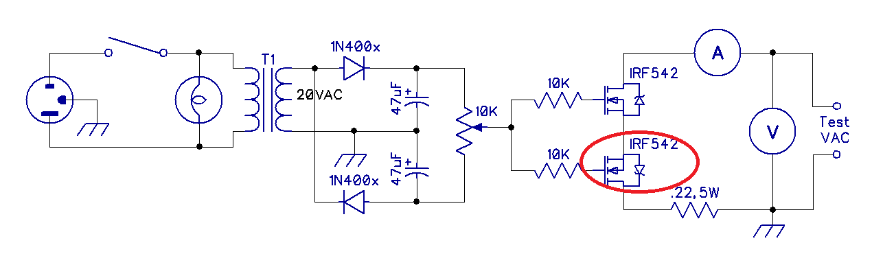
● In “Overvoltage Protection for ac Generators” [Apr 2013, pp 43-46], some of the identified parts are no longer available, or are not available in single unit quantities. Please make the following changes:
C1 — 220 µF, 35 V electrolytic capacitor (Digikey P5166-ND).
DS1, DS7 — Red LED (Digikey 751-1129-ND).
DS3-DS5 — Green LED (Digikey 751-1099-ND).
DS2, DS6 — Yellow LED (Digikey 751-1144-ND).
The original amber LED is no longer available in 3 mm size so that has been changed to yellow.
●In “Overvoltage Protection for ac Generators” [Apr 2013, pp 43-46], the author provided the following update: If you are using the circuit board from Far Circuits, note that they have included the two jumpers I discussed as connection on the board. Thus, you will not be able to use the on-board jumpers as part of the calibration process. Instead, you will have to carefully touch your positive voltmeter probe to the LM-3914-1 pins. The negative lead attaches to the negative foil strip on the bottom of the board where the negative lead of capacitor C1 is attached.
LM-3914-1 pin 6 is for the lower voltage setting (0.35 V dc) and pin 4 is for the higher voltage setting (0.55 V dc). Remember, those are starting voltages and will have to be adjusted a little.
Remember, while making adjustments, avoid contact the leads going to the GFCI and with R5 and U3, including the foil side of the board around those components.- In "Remote Control of Accessories via the Internet" [April 2013, p 31] in the Figure 1 parts list, the K1-K8 SPDT relays should be identified as Digikey part 225-2077-ND or Mouser part 769-JQ1P-12V-F. These are only examples of relays that can be used in this project. Relays should be selected based on the ac or dc voltages and currents required by the devices being switched
May - In “Build a Linear 2 Meter 80 W All Mode Amplifier,” by James Klitzing, W6PL [May 2013, p 30-34], two heat sinks are included in the parts list, but only one is necessary, specifically: Heat sink extrusion 5.375 x 8 x 1.375 inches (Heat Sink USA A008).
June • In “Up Front” [June 2013, page 20], the photo at the upper left corner of the page with the caption "On the road with the tower trailer" is actually a photo of different tower trailer that the author built in the 1970s and towed from California to Vermont. It is not the same trailer shown in the rest of the article.
• In “Forty-Three Million Miles per Watt” [June 2013, page 63], it is stated that the roundtrip distance to the Moon is 756,000. This is an error. The true distance is about 477,714 miles.July In “The Doctor is In” [Jul 2013, pp 54-55], there is a typo in the response to William, W5VDM. The correct formula for the approximate distance to the radio horizon is 1.32 × [height (ft)]0.5. In “The Real Q-Pole” [July 2013, pp 37-38] the spacing between the rods of the Q section is 2 3/4 inches measured at the outer edges of the two elbows, not 1 1/2 inches as shown in the diagram. This is not an electrically critical dimension, but should be noted.
August • “Hands-On Radio” column #127 [August 2013, pp 53-54] mistakenly uses 1.866 for the square root of 3 when the correct value is 1.732. The correct voltage between two phases of a three-phase 120-V system is then 120 x 1.732 = 208 V. Two hundred and forty volts would be supplied in a split-phase system with each phase supplying 120 V.
• In “The August 2013 Rookie Roundup – RTTY” announcement [August 2013, p 82] the photo caption is inaccurate. The operator on the right is Eugene Mah, KK4JRP (now AB4UG). The photo was taken by Thomas Glaab, AJ4UQ, and the club is the Charleston Amateur Radio Society (CARS, not CARC).November In the article “A Cascaded Current Transformer RF Coupler” by Ralph Crumrine, N0KC, which appeared in the November 2013 QST, page 52, the Steward core number shown for transformer T2 is incorrect. The correct part number is 28-0375-400. December In the article, " How Much 'Punch' can You get from Different Modes?" by K. Siwiak, KE4PT and B. Pontius, N0ADL, that appeared in the December 2013 QST, page 30, there is an error in the PSK31 entry of Table 2, which propagates to Figures 3 and 4. In Table 2 last column, PSK31 should be +4.8 dB. In Figure 3 PSK31 should be 7 dB, and in Figure 4 the range for PSK31 should be 2X. -
Issue Feedback January The article “A Transistor Tester in a Tin” [pp 30-31] has three problems. In Figure 1, the sketch of the TO-92 transistor (the lower unit) has its emitter (E) and collector (C) leads reversed. BT1-3 should be AAA size batteries to fit in the Altoids can. The headphone connection, J1, is correct as shown for headphones with dc continuity, such as dynamic headsets. If a crystal earphone is used, the bottom of R7 should be grounded and the earphone connected between the top of R7, in parallel with the emitter, and ground. Note that with this change there will be current drawn from the battery at all times, so at least one battery should be removed when the unit is not being used, or a power switch should be added. February In “Product Review — Four 25 A Switch Mode Power Supplies” [pp 56-59] some updates were not made following Ten-Tec’s replacement of the 941 supply with a current unit. On page 59, under “Lab Testing” in the first column, it should now say: “The supplies here all tested between 110 mV and 490 mV, most in line with the best of supplies reviewed previously.” In the third column it should now say: All of power supplies tested here passed part 15 requirements for conducted emissions. Overall the QJE DX PS30SWII and Ten-Tec 941 were the quietest of the units tested, followed closely by the Jetstream JTPS30M. We have learned that the image we have been describing as AMSAT-OSCAR 51 [see, for example, p 87] is actually a different satellite. ― tnx Drew Glasbrenner, KO4MA March In “Webcam Microscope for the Radio Amateur” [pp 38-39] the name of the author of the referenced article is Jim Koehler, VE5FP, not Joe. In “A Coaxial Vertical for 160 and 80 meter” [pp 30-32] the entry for Section 4 in the caption for Figure 5 should be 3960 not 1960 kHz. In “Hands-On Radio” [pp 59-60] Ed, N5KZW, points out that to bring your workplace up to standard practices for ESD, the best method is to use a static dissipative mat and cuff. These are widely available from distributors such as Digi-Key and Jameco. With their current-limiting series resistance, these are also safer in case of electrical fault. April In "The Doctor is In" the correct call sign of Elwood who contributed the link about meteor pings is WB0OEW. The antenna photo on page 120 of the Apr 2012 issue was taken by Tim Raven, G4ARI. The cover of the Apr 2012 issue should have referred to RMS Titanic, not HMS. In “Level Converter to Allow Full Control of Peripherals by Computer or Radio” [pp 38-40] the ground connection on J4 should go to pin 5, not pin 4. Also the "Hamspeak" item was in error. It should have read:
Null Modem -- An adapter to interconnect two devices both wired as EIA RS-232-C DCEs or DTEs using DSUB25 or DSUB9 connectors. To allow communication, interconnect RECEIVE DATA (pin 3) on one connector to TRANSMIT DATA (pin 2) on the other for either connector type. The SYSTEM GROUND connection should also be interconnected end to end -- pin 7 on DSUB25, pin 5 on DSUB9.
For most devices that require flow control, cross connecting CLEAR TO SEND and REQUEST TO SEND either at each connector, or from end to end, will allow data flow. Some implementations may also require DATA SET READY and CARRIER DETECT at one end connected to DATA TERMINAL READY at the other.
May June In “The 43 Foot Vertical — What’s the Magic,” June 2012, pp 30-31, I was remiss in not mentioning that the 43 foot vertical, as any monopole fed against ground, requires a good radial ground system to be efficient. The radials can be on or under the ground, or can be elevated. If you’re not familiar with the requirements for such a system, please look over the excellent QST article by Rudy Severns, N6LF, on the subject.1— J. R. Hallas, W1ZR, Technical Editor, QST.
1R. Severns, N6LF, “An Experimental Look at Ground Systems for HF Verticals,” QST, Mar 2010, pp 30-33.
July In the 2011 ARRL 10 Meter Contest Results (July 2012, pp 80-83), the DX winner of the Single Operator, Phone Only, High Power category was listed as LP1H (LU5HM, op). This is incorrect. The correct winner was KP2A (KW8N, op). August In “A Digital Interface for Fldigi” [Aug 2012, pp 36-38] Figure 1 shows the connectivity of the output pins of U2 in error. Pin 4 should go to MIC GROUND, pin 5 should go to PTT and pin 6 should be left unconnected.
The miniature audio isolation transformers, T1-T3, are no longer listed by RadioShack. Rick, WA6NUT, suggests the Triad TY-145P as a suitable replacement. It is available from the usual suppliers, including Jameco (www.jameco.com)and Mouser (www.mouser.com).
In “My Tuner Tuned My Antenna — But Now It Doesn’t!” [Aug 2012, p 47] the caption to Figure 1 should say TLW TUNER output, not EZNEC TUNER outputSeptember In “The Uncooperative Tree” [Sep 2012, p 30-32] the value of the inductors in Figure 2 should have been shown as 33 μH.
In “Power Carts for Scouts and Field Operations” [Sep 2012, pp 36-40] switch S3 in Figure 6, shown as a DPDT center-off switch, could be a SPDT center-off unit instead.
October In “The Evolution of DX Spotting” [Oct 2012, pp 71-72] the author noted that he used the work “splitter” when he meant “skimmer” when describing certain terminology related to the Reverse Beacon Network.
In "Those Mysterious Signals" [Oct 2012, pp 37-39] the correct URL in note 4 is wwlln.net/TOGA_network_global_maps.htm. November ● In “Boat Anchor Buddy” [Nov 2012, pp 53-56] there should have been a footnote indicating that PC board files and other layout information is available on the QST in Depth website.
● In “Boat Anchor Buddy” [Nov 2012, pp 53-56] the parts list in the caption of Figure 1 has the values of C5 and C6 reversed, they are shown correctly in the schematic. R11 is missing from the parts list and is a 6800 ohm resistor like R13. In Figure 1, Q7 has the collector and emitter leads reversed. The board layout is correct.
● In “Boat Anchor Buddy” [Nov 2012, pp 53-56] some builders have experienced excess current and heat in the NE555 timer IC. Lower current operation will be achieved by removing R6 from the + 12 V line and inserting it between pin 3 of U1 and the base of Q4. A revised layout drawing is on the QST-in-Depth website at www.arrl.org/qst-in-depth.
● In “Building Inexpensive HF Power Attenuators” [Nov 2012, pp 32-33] the first formula on page 32 should indicate 1.41 A, not 0.71 A.
● In “Have Fun Building the Simplest Transmitter” [Nov 2012, pp 46-49] the author has provided some additional coil data. He notes that his 40 meter L3 is five turns, wound exactly as L2 and that he uses his 40 meter L2 as his 80 meter L3. The value of R1 is not shown. The correct value is 100 kohms, 1 W.
In the “Power Supply Options” sidebar C1 and C2 are 8 μF, 450 V electrolytic capacitors. They are available from Antique Electronics Supply (www.tubesandmore.com), part number C-SA8-450.
● The author of “Distracted Driving and Amateur Radio—A Civil (Law) Perspective” [Nov 2012, pp 81-82] has sent us an update regarding his article. The article includes the statement: “In Illinois, an effort by ARRL officials quickly convinced the legislature to adopt a blanket exemption for Amateur Radio from the measures being considered.” The final legislation (Public Act 97-828) that was adopted does not appear to contain the blanket exemption for Amateur Radio. The blanket exemption has been amended onto another bill that remains in committee and is unlikely to be passed this session but could be reintroduced next year.
December ● In “PSK-31 Operation on 2 Meter FM” [Dec 2012, pp 37-38] in Figure 1, the word “Ring” should be further to the right to line up with the contact for the right channel. The portion of the connector on the far left is the “sleeve.” In addition, the tip should be shown to the right of the ring.
● In “Product Review—Elecraft KX3 HF and 6 Meter QRP Transceiver” [Dec 2012, pp 39-44] the last word of the first paragraph under What’s In The Box on page 39 should be “translator,” not “transistor.”
● In “Life Members Elected” [Dec 2012, p 60] Brad R. Woodward, KG4FUS, was included in the list in error.
Feedback

EXPLORE ARRL
-
On The Air
DXCC Program, W100AW & W1AW QSLs via Bureau, Centennial QSO Party, Operating Specialties, International Grid Chase 2018, Hiram Percy Maxim 150th Birthday Celebration, Cycle 25, Transatlantic, Special Event Stations, Operating Resources, W1AW, Volunteers On the Air, QSL Service, NPOTA, Contests, Awards, Logbook of The World, Amateur Code, Amateur Radio Direction Finding
Licensing, Education & Training
Courses & Training, What is Ham Radio, FCC License Info and Forms, License Certificates, Learning Programs, Youth Licensing Grant Program , Volunteer Examiners, Edu Dept Home, Learning Center Help, Gordon West, Getting Licensed, Newly licensed? Learn More, Volunteer Instructors/Mentors, Amateur Radio in the Classroom
Membership
Member Directory, myARRL, Blind Membership, Join ARRL/Renew Membership, member feedback, Dues Increase FAQ, Techquestion, Please Confirm Your Information, Member Discounts, Member Bulletin, QST Reissue, Membership Certificate, Member Support, ARRL Groups, Connecticut Member Social, Silent Key Submission Guidelines, Login Instructions, Dues Survey, Gift Membership, New Join, 3-Year Special Offer, 2024 Dues Rates
-
Regulatory & Advocacy
State and Local, Volunteer Consulting Engineer Program, Volunteer Counsel Program, CCR Study Information, International, Technical Relations Office, Federal, Volunteer Monitor Resources, Federal RFI Preemption, Antenna Regulation and Zoning, Volunteer Monitor Program
Public Service
NTS Manual, Public Service Resources, Volunteer Form for Deployment Consideration, 2018 Hurricanes, Hurricane Maria - 2017, Hurricane Irma - 2017, Hurricane Harvey Response, Ham Aid, Public Service Honor Roll, 2019 Hurricanes, 2020 Hurricanes, 2021 Hurricanes, Puerto Rico - Caribbean Recovery 2017, Kentucky ARES Summit and Survey, ARES, Hurricanes, Served Agencies and Partners, SKYWARN Recognition Day, NTS
Technology
ARRL References, ARRL Lab, Tech Portal, Radio Technology Topics, Radio Frequency Interference (RFI), Technical Information Service, ARRL Clean Signal Initiative
-
Get Involved
Clubs, Volunteer Opportunities, Youth, Recruiting & Outreach, The ARRL Foundation, Donate to ARRL, Hamfests and Conventions Calendar, Collegiate Amateur Radio
Publications & Online Store
ARRL Publication Dealers, ARRL Store, List all Products, Return Policy, Shipping and Tax, Customer Service/Support, Handbook, Product Notes
About ARRL
Site Index, Centennial, Privacy Policy, ARRL Strategic Plan, Advertising and Other Business Opportunities, ARRL on the Purpose of Amateur Radio, Library, Ideas, Copyright, Organization Structure, Media and Public Relations, Contact ARRL, Visit Us, ARRL Social Media, General Information, Employment Opportunities


ARRL
The National Association for Amateur Radio®
225 Main Street
Newington, CT, 06111-1400 USA
Tel: 1-860-594-0200 | Fax: 1-860-594-0259
Toll-free: 1-888-277-5289
hq@arrl.org