Force 12, C-3S — Adding the Fifth Band
As mentioned in a previous article, the Force C-3S is a very robust Yagi and its design is ideal for extending coverage up to five bands by application of linear resonator techniques. One of the attractive design features is that the Force 12 antenna uses no traps, a buzz word for quite a while among serious DXers. From a mechanical and RF point of view the manufacturers deserve a lot of applause. A few of us in this area have had our C-3S Yagis survive the regular strong and gusty storms that are typical of winters near the most southern tip of Africa.
Now that solar cycle 24 is in sight, so they say, conditions on the higher bands will be picking up. This means it is time to look at the final step in making a Force 12, C-3S a true five band Yagi. After enjoying great results with the addition of 17 meters, the 12 meter modification is a logical next step in expanding the frequency range of this Yagi.
Discussion
Taking a look at the C-3S and reading about the principles of operation, especially the driven element, it is clear that the Open Sleeve is a dedicated three band driver, which does not make any particular provision for 17 meters or 12 meters. One can therefore appreciate that matching is quite poor on both these bands with one exception. Seventeen meters is close enough to 15 meters for built in automatic antenna tuners to keep rigs happy. For this reason the 17 meter modification described in the previous article did not involve any changes to the driven element. On 12 meters it is a different story all together and the mismatch is too much for an automatic antenna tuner to deal with. When you listen to 12 meters it sounds as if the antenna is disconnected. Only a faint background crackle and hardly any signs of signals can be heard, except for the very strongest. The original configuration of a C-3S is shown in Figure 1, and after the 17 meter modification the antenna layout is shown in Figure 2. This is the starting point for adding the 12 meter band.
From the beginning, the same goals were kept in mind as for the addition of the 17 meter band: The fifth band had to be added without cluttering the already quite busy boom. Since making the modifications I am about to describe, I have been getting good reports and enjoying a lot of success during 17 meter and 12 meter openings. More about on-the-air tests later.
The Solution
The solution for adding band five involved two steps. First, there had to be a 12 meter reflector and second, the matching had to be drastically improved.
Reflector
Past experience made it a logical step to add a 12 meter linear resonator to the new 17 meter reflector to change it into a two band reflector. Attaching the linear resonator is quite simple. A nice thing about it is that there is no need for drilling holes in the existing structure. It actually hangs on the element with two clamps and two acrylic hangers. All this and the simplicity of the modification will become clear later.
Referring to the article in QEX “An Accidental Discovery Put to Work,” I will briefly explain what a linear resonator is and highlight its potential in HF antenna applications. The basic principle came from an accidental discovery by Les Moxon, G6XN, the author of HF Antennas for all Locations.
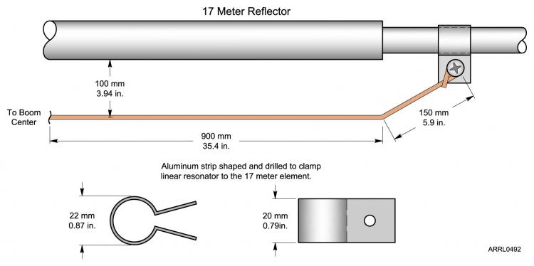
A linear resonator is an LC circuit consisting of a one-turn rectangular shaped coil, shown in the schematic diagram, Figure 3. B-C-E-F is the inductor; resonated by the variable capacitor D. Half of the coil is shared by part of the element B-F. Due to this sharing, a second, higher resonant frequency is obtained over and above the natural resonance of the basic element, A-G. One limitation found was that the second resonance had to be at least 40 percent higher than the basic resonance of the element to which it is attached. This makes the 17 meter reflector ideally suited for a second resonance on 12 meters.
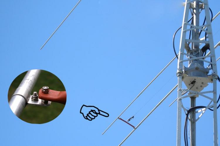
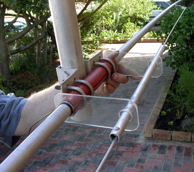
Figure 4 is a photograph showing the main components of a linear resonator. For the sake of illustration, it is shown attached to the 20 meter reflector. Note that the antenna is tilted so that the element runs parallel to the ground with the boom pointing up. The inductor part of the resonator is made of 5 mm diameter solid aluminum rod and consists of two identically shaped halves suspended directly below the 17 meter reflector at a spacing of 100 mm. Total length of the inductor is 1.84 m. The series tuning capacitor is the neatest part of the whole setup: It is a piston type, made of a 500 mm length of 16 mm diameter aluminum tubing, which forms the outer electrode. In Figure 4 the rod can be seen clamped in the tube on the side facing the camera. The rod farthest from the camera, extending from the tube, is the inner electrode. It slides into the tube on acrylic spacers, which insulate it from the tube. The dielectric is formed by the air gap between rod and tube. The resonant frequency of the linear resonator is adjusted by sliding the tube left or right over the rods until the required resonant frequency is found, where it is clamped in position.
Matching
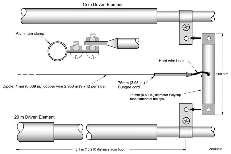
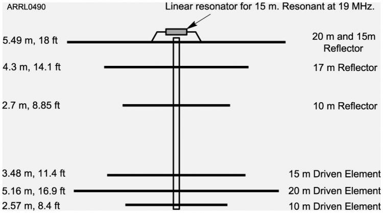
To take care of the poor matching on 12 meters, a half wave dipole made of thin copper wire is suspended between the existing 20 meter and 15 meter open sleeve elements. Supports for the dipole are two insulated spacers mounted between the 20 meter and 15 meter driven elements. This serves a dual purpose as it also provides stability of the elements in windy conditions. If the 17 meter and 12 meter linear resonator modifications aren’t used, this 12 meter device can be installed as a standalone to improve 12 meter matching. After this addition, the receiver came to life and for the first time a match comparable with the basic three bands was found over the entire 12 meter band. This is not a complicated addition to the antenna as will be seen in the detail to follow. Figure 5 shows the antenna configuration after modifications.
Installation
Resonator and Element Clamps
1. Bend the aluminum rods (part A) into two identical shapes as shown in Figure 6. The loops at the ends should be just big enough to take the available hardware for clamping to the 17 meter reflector.
2. Make two aluminum clamps out of the aluminum strip (part C) as shown in Figure 6. Be sure to leave enough material for the Matching Unit clamps described below.
Capacitor
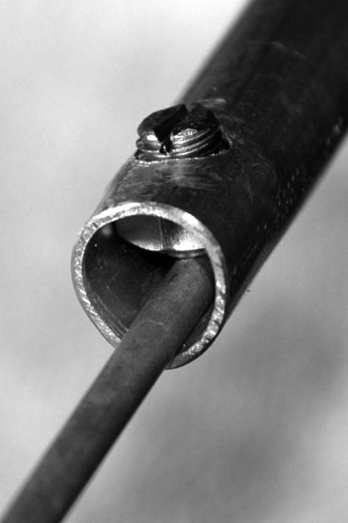
1. Drill a 9 mm hole through one wall of the aluminum tube (part B), near its tip to take an 8 mm stainless bolt (part M). Cut off the head of the 8 mm bolt and slot its shaft so that it can be turned with a screwdriver (see Figure 7).
2. Round the shoulders of an 8 mm nut, using an electric bench grinder. Clamp the tube in a vice and force the nut slightly into the tube. Tightening the nut on to the 8 mm bolt prepared in step 1. This is so that the nut will seat a little into the tube and stay in position on its own. This becomes a clamp so that the rod can be secured in position after tuning.
3. The next two items are acrylic spacers that form the guts of the variable capacitor. Shape one of the blocks (part L) as shown in Figure 8 to form the round “outer” spacer and slip it on to the tip of one of the aluminum rods (part A). This becomes the inner electrode of the variable capacitor. Ensure that the hole in the spacer is just large enough to allow free movement over the rod. Carefully file the outside of the outer spacer to a slight taper for a snug fit in the open end of the 500 mm aluminum tube (part B). This is the end insulator, which supports the aluminum rod inside the tube.
4. Shape the “inner” square insulating block (part L) into a spacer as shown in Figure 8 and slide it over the rod (part A). Carefully file the tips of this spacer so that it will slide freely into the tube. Wind a small piece of self vulcanizing tape (part E) around the aluminum rod, one on either side of the inner spacer to keep it in position as close as possible to the tip of the rod.
Hangers for Suspending Resonator from Element
1. Cut and drill two hangers out of the pieces of acrylic (part D) as shown in Figure 9. The small notches are there to clear rivet heads when sliding the hangers over the element.
Attaching the Linear Resonator
1. Slip the two acrylic hangers on to the 17 meter element, one on either side of the boom as seen in Figure 10 and Figure 4. Keep them from sliding around by fastening cable ties to the element, one on each side of a hanger.
2. Place the two aluminum clamps made in the previous section loosely over the 17 meter element, one on each side of the boom at a distance of about 900 mm from the boom. These will be used to attach the looped ends of the aluminum rods (part A) to the element.
3. Assemble the linear resonator by sliding the tube over the rods taking care to fit the spacers into the tube. Carefully string it through the holes in the acrylic hangers. Use stainless steel hardware (part J) and the clamps already in place to clamp the looped ends of the aluminum rods to the 17 meter reflector as shown in Figure 10. This will form the basic linear resonator with a total length of 1.8 meters. Make sure that there will be a gap of about 15 mm between the rod tips where they meet below the boom to avoid shorting inside the tube.
• It is worth mentioning that there is quite a bit of adjustment available for moving the tube from extreme left to right over the aluminum rods as shown in Figure 10.
Tuning the Linear Resonator
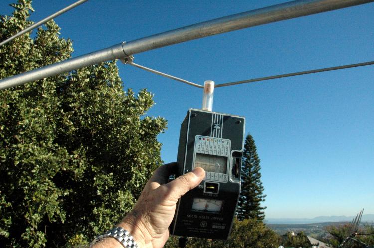
The calculated resonance of a 12 meter reflector is 22.5 MHz. This frequency can be picked up by holding the sensing coil of an absorption dip meter near the farthest end of the inductor as shown in Figure 11. Slide the lock screw towards the hanger to lower the resonant frequency (more capacitance) or away from the hanger to increase it. Tighten the lock screw to secure the tube in position after finding the 22.5 MHz resonant frequency.
If everything works out, the inner electrode of the variable capacitor should be a loose fit in the tube to allow lateral movement. The linear resonator is springy and once locked in position, no matter how much the wind shakes the 17 meter element around, it will return to the set frequency. I have checked the set resonance on various occasions and it never needed any readjustment.
12 MHz Matching Unit Construction
Dipole Supports / Element Spacers.
1. Make four aluminum clamps out of the remaining aluminum strip (part C). Bend these into the shape of clamps.
2. Attach the clamps to the 15 and 20 meter elements opposite each other at a distance of 3.1 meters from the boom (see Figure 13). Note that the 20 and 15 meter elements have different diameters where the clamps are mounted. Make sure there will be a tight fit around the elements at the positions where the clamps will go.
3. Cut two 200 mm pieces of 15 mm diameter Polycop (part G). Prepare the spacers by heating the pipe ends using a hot air gun and flatten the ends while hot in a bench vice.
4. Drill the Polycop spacers and mount them to the clamps on the driven elements. Drill a hole through the center of each spacer for the dipole support hooks. An assembled spacer is shown in Figure 12. The nuts holding the ends of the insulator should be Nylocks (part K) and not tightened all the way, so that there is some play for movement in windy conditions.
Dipole
1. Find the center of the 4 meter length of copper wire (part F), wind it twice around the boom exactly half way between the 20 and 15 meter driven elements and tape (part E) it in position.
2. Fold the dipole ends back and attach the two short lengths of Bungee cord (part H).
3. Shape two strong wire hooks (part I) and assemble the element as shown in Figure 13.
4. Stretch the Bungee cords and hook the stiff wires into the center holes of the spacers. This will string the dipole tightly between the 15 and 20 meter driven elements, with some elasticity. A dipole length of 2.95 meters per side will be a good starting point before fine tuning. Figure 14 gives a view of the finished dipole.
Fine Tuning the 12 Meter Dipole
Connect an antenna analyzer to the antenna feed point and check SWR at the 12 meter band center. The dipole has a sharp response, but due to the 12 meter band being only 100 kHz wide this is not important at all. The addition of the 12 meter dipole in the Open Sleeve does not affect matching on the three basic bands, 20, 15 and 10 meters.
Make length adjustments as needed. Lengthening both sides by 10 mm at a time will lower the center frequency. Alternatively, shorten the dipole in small steps to increase the frequency until a 50 ohm match is found at the band center. A match of better than 1.2:1 is possible without any difficulty.
Testing on the Air
Numerous checks of front to back (F/B) ratios under various conditions showed a consistent ratio of 2 to 3 S-units on transmit and receive, with very deep nulls off the sides on all five bands. There are a few friends in this area using 3 element triband trap Yagis. Comparative reports from DX stations on the three main bands were very encouraging and in most cases the modified C-3S performed as well as the trap tribanders. Considering that this is a Yagi with two active elements on each band, the F/B ratio was not as dramatic as in the case of trap tribanders. All my concerns that the modifications may have had a negative influence on the performance of the antenna on the three main bands were ruled out by reports received on the air. I could find no local stations using directional antennas on 17 meters and 12 meters to compare signals with. But from the good reports received and the ease of being heard, I am seriously looking forward to cycle 24 so that I can make farther progress with my 12, 17 and 30 meter band DXCC. The antenna at my home station is shown in Figure 15 with Table Mountain in the background.
Metric Conversions
The formulas for converting the metric measurements listed here to English measurements are as follows:
a. To convert millimeters to inches: mm/25.4 = inches
b. To convert millimeters to feet: mm/304.8 = feet
c. To convert meters to feet: m/0.3048 = feet
There are also a number of places on the Internet that have conversion calculators, such as: www.worldwidemetric.com/metcal.htm. Google also has a calculator as part of its function. Type in a conversion, such as “500 mm to inches” and Google will display the inches value.
Parts List — 12 Meter Linear Resonator
A. Two lengths of aluminum rod, 1 meter each of 5 mm diameter. Any aluminum rod close to these dimensions would do, provided it is soft enough to bend without cracking.
B. 500 mm length of 16 mm diameter aluminum tubing of 1 mm wall thickness.
C. Aluminum strip 20 mm wide × 1 mm thick. High tempered springy aluminum will be ideal for this. Total length needed is about 600 mm.
D. Two pieces of 160 mm × 60 mm × 6 mm clear acrylic.
E. Self vulcanizing insulation tape.
F. Approximately 4 meters of 1 mm diameter soft enamel coated copper wire.
G. 500 mm length of 15 mm diameter Polycop tube. This material is used for high pressure water conduit in the building industry.
H. A short lengthof 6 mm diameter Bungee cord.
I. A 100 mm piece of 2 mm diameter hard copper wire.
J. A few small stainless steel nuts and bolts of the variety found in any well stocked junk box.
K. Two stainless steel bolts and Nylock nuts. This is not critical and depends on what is available for clamping the Polycop tubes to the elements.
L. Two small blocks of acrylic 25 mm × 25 mm × 6 mm.
M. One 8 mm × 15 mm stainless steel bolt and nut or any similar hardware.
• Absorption Dip Meter
• Cable ties
• Heat gun
All photos and drawings by Vidi la Grange, ZS1EL.
Vidi la Grange, ZS1EL, studied Physics at the University of Stellenbosch, near Cape Town, South Africa and graduated at the end of 1961. He was first licensed as ZS1AL, during that time. His interests in Amateur Radio center around experimental antenna work and building of various pieces of station gear. His favorite mode is CW and Vidi has been a member of the First Class CW Operators Club since April 1960. He is a contributor to QEX, and a member of the SARL. Vidi enjoys operating in DX contests and was top scorer for the 2007 ARRL 10 Meter Contest, mixed mode high power, single operator category. He married Hester, N4MPQ, in 1996 after a DX CW romance. Now retired, Vidi is living in Somerset West, a village with a view of the Atlantic Ocean and the City of Cape Town, about 35 km to the west. They have four adult children, three sons and a daughter. Vidi can be contacted at P O Box 301, Somerset Mall, 7137, Republic of South Africa.
Vidi la Grange, ZS1EL, “An Accidental Discovery Put to Work,” QEX, Mar/Apr 2006, pp 46-50
HF Antennas for all Locations is available from your local ARRL dealer, or from the ARRL Bookstore, ARRL order no. 4300. Telephone toll-free in the US 888-277-5289, or 860-594-0355, fax 860-594-0303; www.arrl.org/catalog; pubsales@arrl.org.
All figures referenced in this article are available in full sized versions in the file C3S_12mModArt.pdf that can be downloaded from the QST binaries site.
Vidi la Grange, ZS1EL
Photo Gallery
-
 Figure 15 — A bea...
-
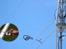 Figure 14 — Photo...
-
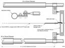 Figure 13 — Mecha...
-
 Figure 11 — Bring...
-
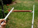 Figure 12 — Photo...
-
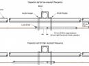 Figure 10 — The h...
-
 Figure 9 — Detail...
-
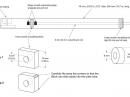 Figure 8 — Detail...
-
 Figure 7 — A clos...
-
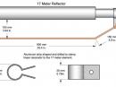 Figure 6 — Detail...
-
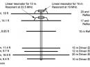 Figure 5 — Diagra...
-
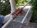 Figure 4 — A comp...
-
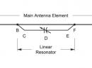 Figure 3 — A mech...
-
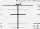 Figure 2 — Diagra...
-
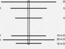 Figure 1 — Diagra...


Back


