The Field Day Flag Pole Vertical
The Orange County New York Amateur Radio Club (OCARC) started preparations for Field Day 2007 with a meeting at our Field Day location: Cronomer Hill Park in Newburgh, New York. There are many reasons to set up in Cronomer, among them being it is out of the way, is a relatively high location with an elevation of approximately 700 feet and there is a 30 foot tall observation tower that is great for tying off dipoles and to help support our military surplus crank-up tower.
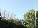
There is also a flag pole -- sans flag --- standing near the observation tower on top of the hill. One of the long time club members mentioned that, for years, there has been talk of trying to load into the flag pole. But no one has ever really wanted to try it. Not being one to back down from a challenge, I said that I would attempt to load the flag pole to skeptical eyes. Thinking a little deeper on the subject, what better time to attempt this than Field Day?
The idea of Field Day is to operate under adverse conditions, correct? Well, let's say that there was flooding in the Newburgh area and I was stuck in Cronomer Park. And let's say I happened to have an HF radio with me and an antenna tuner, but no antenna. Or even better -- let's say I moved into a neighborhood with restrictions on antennas but not on flag poles. The flag pole project was starting to sound really good.
It'll Never Get Off the Ground
"But wait!" you might say, "The flag pole is grounded!" This is true. The flag pole is at ground potential -- at dc and low frequency ac. At RF, however, only the bottom of the flag pole is at ground potential. Thinking back on a 30 year career in Broadcast Engineering, the FCC used to allow shunt fed radiators for AM radio stations and I had once tuned one up. Most AM broadcast stations use towers (antennas) that are series fed, sit on insulators and have a rather high RF potential at the base of the tower. Shunt fed AM towers are grounded at the bottom. The RF feed point is at a specific distance up from the base of the tower and is fed from a "slant wire" that connects this feed point to the tuning unit at the base of the tower. The feed point is chosen by analyzing the RF current distribution along the tower and picking a point that will present a reasonable driving-point impedance to the system. The RF current will not be grounded because of the wavelength of the signal driving the antenna will distribute itself over the length of the flag pole and the structure will radiate. (For more information on shunt-feeding see The ARRL Antenna Book chapter on "Low-Frequency Antennas.")
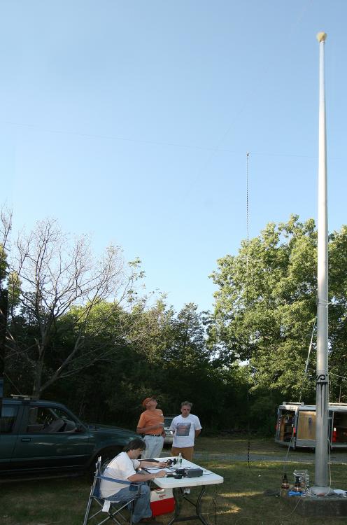
The Cronomer flag pole is approximately 45 feet tall. Being that there would be a physical limitation to the height of the feed point, ie, the ladder we would have on site would be only 8 feet tall, meant that the feed point could realistically be no higher than 10 feet off the ground.
Using EZNec, I proceeded to model the flag pole. Since we were intending only to play with this idea, I used the default value for the diameter of the vertical radiator in EZNec. I also modeled it over real ground and, since we were playing, did not include ground radials.
Antenna Modeling Proves the Point
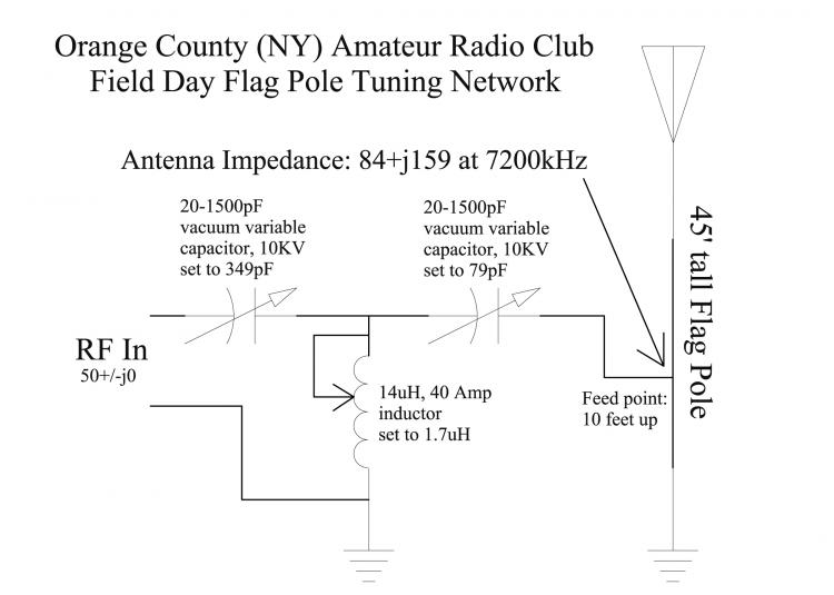
Thinking that since the sunspot cycle is low, the best chance to make contacts would probably be on a lower band. I first modeled the antenna at 20 meters. That returned an absolutely ridiculous RF feed-point impedance of something like 549 ohms resistive at 590 ohms inductive reactance. Eighty meters showed a workable impedance of 18 ohms resistive at roughly 280 ohms capacitive reactance. Forty meters was a winner: 84 ohms resistive at 159 ohms inductive at 7200 kHz. That would be easy to transform down to 50 ohms nonreactive.
I decided that I would determine the component values to tune the flag pole by designing a +90 degree T network to match the transmitter to the pole. A +90 degree T network consists of two capacitors in series between the transmitter and antenna (in this case, because the antenna is inductive), with a shunt inductor connected between the capacitors and ground. The shunt component determines the primary phase shift, so since this shunt is an inductor, this is a +90 degree network. The basic idea is that the capacitor on the antenna side is adjusted to a capacitive reactance value opposite to the inductive reactance value exhibited by the antenna, thus canceling the antenna's inductive reactance, leaving you with a pure resistance. The shunt coil acts as a transformer to bring the value of resistance down. The capacitor on the transmitter side is intended to cancel the reactance presented by the shunt inductor and to touch up the resistance.
Initial calculated values came out to be 349 pF for the input cap, 1.7 microH for the shunt inductor and 79 pF for the output capacitor.
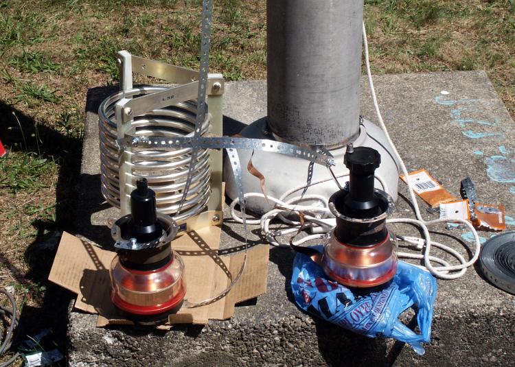
Not knowing if we would actually try to transmit with the flag pole and also not knowing if anyone would be bringing along a linear amplifier, I decided to play it safe and borrowed a few components from WOR Radio's transmitter-spare-parts room. I figured vacuum variable capacitors rated at 10 kV and a coil rated at 40 A would be rather hard to blow up if presented with 1.5 kW.
Matching Contraption
On Field Day, Stan Labinsky, WA2PUQ, and I proceeded to build the Rube Goldberg at the base of the flag pole. First, we attached a length of plumbing hanging strap to the pole about 10 feet up using a large hose clamp. We then started to assemble the tuning network at the bottom of the pole, using a piece of cardboard for an insulator to keep one capacitor off ground and a plastic bag for an insulator for the other capacitor. The coil comes on an insulated form and would just sit there. We also connected a length of plumbing hanging strap to the very bottom of the pole with a large hose clamp. We used Stan's MFJ antenna analyzer to set the capacitors and inductor to the correct values at 7200 kHz.
We connected the components, then connected Stan's MFJ antenna analyzer to the input, set the analyzer for about 7200 kHz and -- saw a resistive component returned of 0 ohms! A dead short! I started to get up to get my laptop and run EZNec again, thinking I had really missed something, when Stan said "Hey -- that's not bad -- no, now it's showing a short again." Looking at the analyzer, it became obvious we were seeing some type of modulation -- and then correlated it with one of our members calling CQ Field Day. He was operating on 7338 kHz. When he stopped transmitting, the analyzer was giving us a reading. And it wasn't half bad. We were looking at a VSWR of less than 6:1.
As I said earlier, I modeled this antenna as something we were playing around with. I did not include the plumbing strap that was connecting 10 feet up to the RF feed point. Therefore, I did not account for the capacitance this strap would introduce in the feed point impedance. We made a few adjustments of the capacitors and attained a 1:1 VSWR, with an impedance reading of 50 ohms nonreactive. But would it work?
Not Quite a Full Gallon
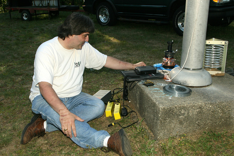
OCARC club member Joe Cupano, NE2Z, had brought along his low power (QRP) radio, so we plugged this into the UHF connector at the input to the tuning network. At 1 W, we were seeing a perfect VSWR. Same thing at 5 W. We also noted that we were hearing a lot of signals very well. Joe likes to work QRP CW and he started calling CQ Field Day in CW on 40 meters right there at the base of the flag pole. His first contact was with a station in North Carolina!
I left Cronomer shortly after Joe made his first contact, returning Sunday around 11:30 AM to prepare to take things down. To my surprise, Joe was still using his QRP rig into the flag pole, had extended the RF cable on the tuning network input to a nearby table and had filled several log sheets since the night before! I guess tuning up the flag pole was a good idea and we proved that you can take a grounded pole and make it into an antenna.
This year, I'm going to put together a slightly smaller -- and neater -- tuning network to load into the pole. And perhaps we'll add some ground radials. If conditions are good, we may want to consider using the flag pole on 12 meters, as an impedance run on EZNec shows a resistance around 51 ohms. Having a permanent on-site vertical antenna has just turned into a big plus for OCARC.
Thomas R. Ray III has been a licensed ham since 2004, upgrading to Extra in May of 2007. While being a "newbie" to ham radio, he has been a Broadcast Engineer for 30 years and is Vice President/Corporate Director of Engineering for Buckley Broadcasting/WOR Radio in New York City. He is President of the Orange County (NY) Amateur Radio Club and is certified as a Professional Broadcast Engineer by the Society of Broadcast Engineers. His vanity call takes some explaining: Since he has spent 30 years in broadcasting, the W represents being east of the Mississippi. The 2 represents where he was first licensed, New York. Here is where it gets rough. T for Tango. He can't dance. And his wife doesn't buy the double Romeo line.
Thomas R. Ray III, W2TRR
Photo Gallery
-
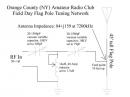 This is the schem...
-
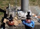 It isnt pretty, b...
-
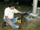 Joe Cupano, NE2Z,...
-
 Stan Labinsky, WA...
Back


