The Force 12 C-3S Yagi -- A 17 Meter Modification
The Force 12 C-3S is a very robust Yagi that uses no traps, which has caused a lot of interest among DXers. I have had my C-3S for about 2 years and even trying their best, our strong northwesterly winter winds could not harm it. Curious about whether the CS-3S could be used on other bands, I tried to load it up directly on 17 meters. When doing so, I was quite surprised that the antenna had slightly more gain off the back than the front! I confirmed this by many front-to-back checks both on receive and transmit. This curious behavior made me believe that a 17 meter modification was possible. I developed the following modifications and have been enjoying a two element Yagi on four bands instead of only three. The modification is not very complicated and once all the components have been prepared, should not take more than a morning to install and tune.
Background
Taking a look at the C-3S and reading about the principles of operation, it is clear that the C-3S is not designed for 17 meters. It is therefore understandable that the SWR is quite high, but not impossible for the built-in antenna tuners of my Kenwood TS-930 and Yaesu FT-1000MP HF transceivers or my Yaesu FL-7000 linear amplifier. The main issue on 17 meters is that there is no dedicated parasitic element as on the other three bands.
The basic C-3S is a two element Yagi with interlaced reflectors for 20, 15 and 10 meters. The driver uses a very efficient, patented, open sleeve system that does an excellent job of matching throughout the three main bands. Considering the overall length of the 15 meter reflector, which is 23.88 feet (7.28 m), I made a few calculations and found the answer to the teasing question about direction reversal quite logical. The particular length of the 15 meter reflector has a calculated resonant frequency of 20.3 MHz, which is close to the length of a director on 17 meters. Using EZNEC 3.0 antenna modeling software, I was able to confirm my thoughts about the antenna behavior.
Now that I understood the antenna better as it came out of the box, I started to do some “out of the box” thinking in search of a solution. What I had in mind was an antenna that worked equally well on four, instead of only three bands, without cluttering the already busy boom any further and, of course, beaming in the same direction on all bands. Since making the modifications I am about to describe, I have been become quite addicted to the 17 meter band, especially during this low period in the sunspot cycle. As the sun sets and the MUF gradually drops, 17 meters stays workable well after signals on 15 meters have faded completely into the noise!
Modifying the CS-3
With my objective in mind and taking a fresh look at the antenna, I decided to leave the open sleeve triband driver as is. The mismatch was not so bad that it was beyond the ability of the built-in antenna tuners to load on 17 meters. Further, the rig did not sound deaf as if there were a complete driver mismatch. I turned my attention to the reflector configuration.
Past experience with the successful application of linear resonators to 20 and 15 meter, two element Yagis, sent my thoughts in that direction and amazingly, the solution was right there. What if I change the existing 15 meter reflector into a dedicated 17 meter reflector and add a 15 meter linear resonator to the 20 meter reflector. To attach a linear resonator is quite simple since there is no need to drill holes in the existing structure. It actually hangs on the element with two clamps and acrylic hangers as will be explained later.
Referring to my article on linear resonators, I will review what a linear resonator is and its uses in HF antenna applications. The basic principle came from an “accidental discovery” by Les Moxon, G6XN, the author of HF Antennas for all Locations.
A linear resonator is an LC (inductor-capacitor) circuit consisting of a one-turn rectangular shaped coil, shown in the schematic diagram, Figure 1. B-C-E-F is the inductor; resonated by the variable capacitor D. Half of the coil is shared by part of the element B-F. Due to this sharing, a second, higher resonant frequency is obtained over and above the natural resonance of the basic element, A-G. One limitation found was that the second resonance should be at least 40 percent higher than the basic resonance of the element to which it is attached. This makes the 20 meter reflector ideally suited for a second resonance on 15 meters.
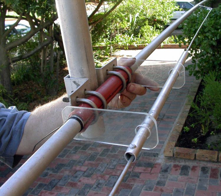
Figure 2 is a photograph showing the main components of a linear resonator. Note that the antenna is tilted so that the 20 meter reflector runs parallel to the ground with the boom pointing up. The inductor part of the resonator is made of solid aluminum rod and consists of two identically shaped halves suspended directly below the 20 meter reflector. Total length of the inductor is 17.72 feet (5.4 meters) and it is suspended 4 inches (100 mm) below the element. The series tuning capacitor is the most interesting part of the whole setup: It is a piston type, made of a 20 inch (500 mm) length of aluminum tubing, which forms the outer electrode. In Figure 2 the rod can be seen clamped in the tube on the side facing the camera. The rod farthest from the camera is the inner electrode. It slides into the tube on acrylic spacers, insulating it from the tube. The dielectric is formed by the air gap between rod and tube. The resonant frequency of the linear resonator is adjusted by sliding the tube left or right over the rods until the required resonant frequency is found and then clamping it in position, but more about this later.
Converting the 15 Meter Reflector into a 17 Meter Reflector
The first step in adapting the CS-3S for use on 17 meters is to convert the 15 meter reflector into a 17 meter reflector using the following procedure:
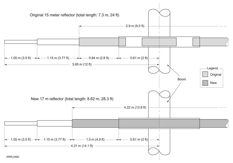
- Take the element apart by drilling out all the rivets except for those holding together the two end sections on each side. Refer to Figure 3 showing the element before and after modification.
- Remove the short inner liner of the element originally used for extra rigidity. It will not be used again as it will be replaced by the new tubing (part A), which will run right through the element center.
- Apply a thin coating of conductive grease to the middle 4 feet (1.2 meters) of the new tubing, before sliding it through the 0.75 inch (19 mm) diameter center section. Position it so that 4.9 feet (1.5 meters) are exposed at either side. Drill and pop rivet the new center part in position.
- Replace the tips and put the element together again so that the new total length per side is 14.1 feet (4.31 meters). Note that the new, longer piece of tubing extends right through the center as shown in Figure 3 to give extra rigidity to the new, longer element.
Adding 15 Meters to the 20 Meter Reflector
Once the 15 meter reflector conversion is complete, modify the 20 meter reflector as follows:
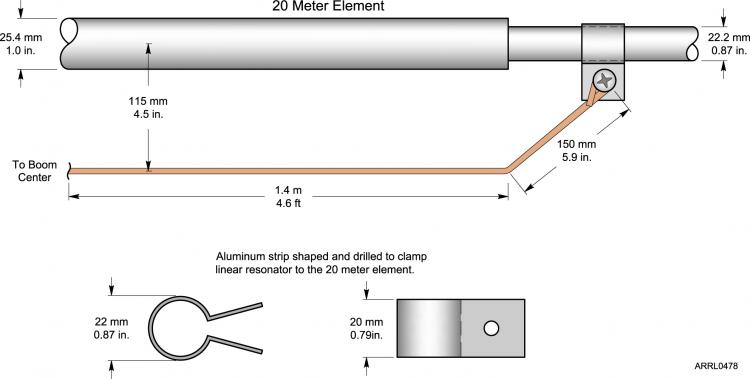
- Bend the aluminum rods (part D) into two identical shapes as shown in Figure 4. The loops at the ends should be just big enough to take the available hardware for clamping to the 20 meter reflector.
- Bend and drill two aluminum clamps out of the aluminum strip (part F) as shown in Figure 4.
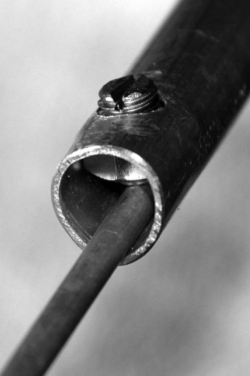
- Cut off the head of the bolt (part G) and slot its shaft so that it can be turned with a screwdriver. Drill a 0.35 inch (9 mm) hole through one wall of the aluminum tube (part E) near its tip to take this bolt (see Figure 5).
- Round the shoulders of the nut (part G) using an electric bench grinder. Set the nut into the tube by clamping the tube in a vise and tightening the bolt onto a piece of the aluminum rod (part D), as shown in Figure 5. This seats the nut in the tube and holds it in place. This becomes a clamp so that the rod can be secured in position after tuning. Take a look at the end of the tube closest to the camera in Figure 2.
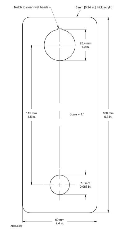
- Cut and drill the two hangers out of the pieces of acrylic (part I) as shown in Figure 6. The small notches are there to clear rivet heads when sliding the hangers over the element.
- The next two items are spacers used to form the internal components of the variable capacitor.
- Outer Insulator Block (part J)
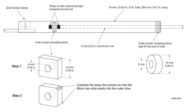
Shape an acrylic block as shown in Figure 7 and slip it on to the tip of one of the aluminum rods (part D), which becomes the inner electrode of the variable capacitor. Ensure that the hole in the block is just large enough to allow free movement over the rod. Carefully file the outside of the block to a slight taper for a snug fit in the open end of the aluminum tube (part E). This is the end insulator that supports the aluminum rod inside the tube. - Inner Insulator Block (part J)
Shape an acrylic block (part J) into the inner insulating block, also shown in Figure 7, and slide it over the rod. Carefully file the tips of this spacer so that it will slide freely into the tube (part E). Wind a small piece of self vulcanizing tape around the aluminum rod, one on either side of this inner spacing block to keep it in position as close as possible to the tip of the rod.
- Outer Insulator Block (part J)
Attaching the Linear Resonator to the 20 Meter Reflector
- Slip the two acrylic hangers on to the 20 meter element, one on either side of the boom as seen in Figure 2. Keep them from sliding around by fastening a cable tie to the element, one on each side of a hanger.
- Place the two aluminum clamps over the element, one on each side of the boom. These will be used to attach the looped ends of the aluminum rods to the 20 meter element.
- Assemble the linear resonator and carefully string it through the two outside holes in the acrylic hangers. Use the stainless steel hardware (part H) and clamps made earlier to clamp the looped ends of the aluminum rods to the 20 meter reflector as shown in Figure 4. Position the clamps about 4.6 feet (1.4 meters) from the boom in each direction, making the total space between them 9.2 feet (2.8 meters). When properly installed there will be a gap of about half an inch (15 mm) between the rod tips inside the capacitor tube.
- This arrangement provides a wide adjustment range by sliding the aluminum tube over the rods to adjust resonance, as shown in Figure 7.
Tuning the Linear Resonator
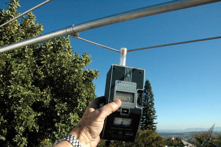
The calculated resonance of a 15 meter reflector is 20 MHz. This frequency is set by holding the sensing coil of an absorption dip meter near the farthest end of the inductor as shown in Figure 8. Sliding the tube in the direction of the grub screw increases the resonant frequency. Tighten the grub screw to lock it in position after finding the 20 MHz resonant frequency.
If everything works out, the inner electrode of the variable capacitor should be a loose fit in the tube to allow lateral movement. The linear resonator is springy and once locked in position, no matter how much the wind shakes the parent element around, it will return to the set frequency. I have checked the set resonance on various occasions over time and it never needed any readjustment.
Testing on the Air
I ran numerous checks of front-to-back ratio under various conditions. The modified antenna showed a consistent ratio of 2 to 3 S-units on transmit and receive, with very deep nulls off the sides on all four bands. There are a few friends in this area using three element triband trap Yagis. Comparative reports from DX stations on the three main bands were very encouraging and in most cases the modified C-3S performed as well as the trap tribanders. The only notable difference was that the front-to-back ratio was not as dramatic as in the case of trap tribanders. All my concerns that the modifications may have had a negative influence on the performance of the antenna on the three main bands were ruled out by reports received on the air. I could find no local stations using directional antennas on 17 meters to compare with, but from the antenna’s great success on this band, 17 meters soon became my favorite.
Since I made the changes to my C-3S, two other Force 12 C-3S Yagis have been modified and used for trials in this area; one belongs to Kosie, ZS1SR, and the other to Sam, ZS1OA. Both are very happy with the performance of their antennas and I regularly hear about the fun they’re having and good reports they are getting from DX stations.
Future Plans
Future plans include improved performance on 12 meters so that the Yagi will have two element performance on five DX bands.
Parts List
A. Aluminum tubing, 0.62 inch (15.8 mm) diameter, 14 feet (4.2 meters) long. Ensure that the wall thickness is such that the other parts of the element will be able to slide into it.
B. A dozen or more pop rivets.
C. Conductive grease.
D. Two lengths of aluminum rod, 5 feet (1.5 meters) long and 0.2 inches (5 mm) in diameter. Any available aluminum rod close to these dimensions would do, provided it is not too hard to bend without cracking.
E. One 19.7 inch (500 mm), 0.63 inch (16 mm) outer diameter length of aluminum tubing of 0.04 inch (1 mm) wall thickness. A piece of the tubing removed from the 15 meter reflector could be used for this purpose, but if you ever wish to restore the antenna to its original condition it is best to find a fresh piece.
F. One 0.8 inch (20 mm) wide by 0.04 inch (1 mm) thick aluminum strip. High tempered springy aluminum will be ideal for this. Total length needed is about 8 inches (200 mm).
G. One 0.3 inch (8 mm) × 0.6 inch (15 mm) stainless steel bolt and nut or any suitable hardware close to this.
H. Two stainless steel bolts and Nylock nuts. This is not critical and depends on what is available for clamping the aluminum rods to the 20 meter reflector.
I. Two 6.3 inch (160 mm) × 2.4 inch (60 mm) × 0.24 inch (6 mm) pieces of clear acrylic.
J. Two small blocks of acrylic 1 inch (25 mm) × 25 mm × 0.25 inch (6 mm).
K. A small piece of self vulcanizing insulation tape.
L. Absorption Dip Meter
All photos and drawings by Vidi la Grange, ZS1EL.
Vidi la Grange, ZS1EL, studied Physics at the University of Stellenbosch, near Cape Town, South Africa and graduated at the end of 1961. He was first licensed as ZS1AL, during that time. His interests in Amateur Radio center around experimental antenna work and building of various pieces of station gear. His favourite mode is CW and Vidi has been a member of the First Class CW Operators Club since April 1960. He is a contributor to QEX, and a member of the SARL. Vidi enjoys operating in DX contests and was top scorer for the 2007 ARRL 10 Meter Contest, mixed mode high power, single operator section. He married Hester, N4MPQ, in 1996 after a DX CW romance. Now retired, Vidi is living in Somerset West, a village with a view of the Atlantic Ocean and the City of Cape Town, about 35 km to the west. They have four adult children, three sons and a daughter.
V. la Grange, ZS1EL, “An Accidental Discovery Put to Work,” QEX, Mar/Apr 2006, pp 46-50.
Available from your local ARRL dealer, or from the ARRL Bookstore, ARRL order no. 4300. Telephone toll-free in the US 888-277-5289, or 860-594-0355, fax 860-594-0303; www.arrl.org/shop/; pubsales@arrl.org .
All figures referenced in this article are available in full sized versions in the file C3S_17mModArt.pdf that can be downloaded from the QST binaries site.
Vidi la Grange, ZS1EL
Photo Gallery
-
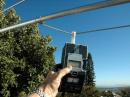 Figure 8 Using a...
-
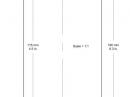 Figure 6 Constru...
-
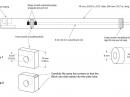 Figure 7 Constru...
-
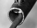 Figure 5 A close...
-
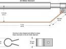 Figure 4 Details...
-
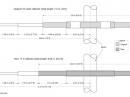 Figure 3 Details ...
-
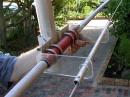 Figure 2 The 15 ...
-
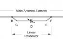 Figure 1 Schemat...

Back


