The Issue of Power-Line Noise
A Smarter Approach
I. Introduction (By Mike Gruber, ARRL Laboratory)
Although the problem has been around since the dawn of radio communications and broadcasting, power-line noise is on the rise. The proliferation of electrical and electronic devices that are potential victims of power-line noise, coupled with today's increased dependence on mobile and wireless communications, have each contributed to this increase. Dealing with a power-line noise complaint does not have to be time consuming or expensive -- and it's the law! A little knowledge can go a long way toward avoiding a fine from the FCC.
Power-line noise can interfere with radio communications and broadcasting. Essentially, the power-lines or associated hardware improperly generate unwanted radio signals that override or compete with desired radio signals. Power-line noise can impact radio and television reception -- including cable TV head-end pick-up and Internet service. Disruption of radio communications, such as amateur radio, can also occur. Loss of critical communications, such as police, fire, military and other similar users of the radio spectrum can result in even more serious consequences.
Let's now take a look at power-line noise, and how to best handle a complaint in a timely and economic fashion.
The Cause of Power-Line Noise
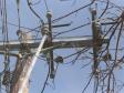
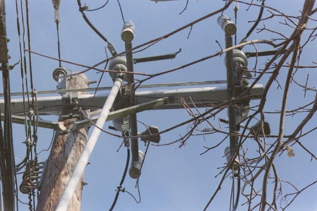
Virtually all power-line noise, originating from utility company equipment, is caused by a spark or arcing across some power-line related hardware. A breakdown and ionization of air occurs, and current flows between two conductors in a gap. The gap may be caused by broken, improperly installed or loose hardware. Typical culprits include insufficient and inadequate hardware spacing such as a gap between a ground wire and a staple. See Figures 1 and 2. We'll be discussing more specific causes of power-line noise in a later section.
Note: The terms "gap" and "conductors" should be interpreted broadly in this case. While not a source of power-line noise, a gap can exist in the commutator of a motor. A gap can also exist between insulator units and other parts of a utility structure. In some cases, the "conductor" can be the wood on the utility pole.
A brief mention should be made concerning corona. Contrary to a common misconception, corona discharge is rarely, if ever, a source of power-line noise. Corona discharge is defined as the partial breakdown of the air that surrounds an electrical element such as a conductor, hardware or insulator. In reality it is typically nothing more than a minor annoyance, as the noise caused by it is usually confined to lower frequencies. This noise does not propagate very far from the source because it is a low-current phenomenon that does not couple into the adjacent wires.
You've Received A Complaint -- What Next?
You've received a power-line noise complaint and investigated it. Based on your investigation, you've now concluded the problem is truly power-line noise. What next? The good news is locating and correcting most power-line noise sources is not particularly difficult or expensive. Proper training and equipment can make most cases a real snap. Let's now explore some of the best ways to handle these types of complaints -- from dealing with the customer to finding and fixing the noise source.
First, let's examine the fundamental issue of why we should care about a radio or television interference complaint in the first place. After all, aren't most utility lines and hardware associated with this type of complaint delivering electric power as they are intended?
-
-
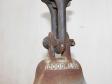 Figure 1
-
 Figure 2

II. Why Care? (By Ed Hare, ARRL Laboratory Manager)
The busy utility executive has to juggle a lot of tasks everyday. Radio/television interference is probably not very high on his or her priority list. This article may help change that. In many cases, a bit of work up front can save a lot of work later. Ensuring that his or her company has a workable program to address its responsibilities with regard to interference, in the long run, will be the most cost-effective solution. Fixing the problem is actually in the utility's best interest. Let's take a look at a few of the specifics as to why:
- It's a matter of customer service. Interference can severely impact a person's quality of life, and that person is almost always a utility customer. Most utilities take great pride in their customer-service programs.
- Radio noise is actually caused by some sort of equipment defect. In some cases, the noise is the most obvious evidence of the problem. While it doesn't happen often, such a defect can fail altogether and drop a live line on the ground. If a good interference resolution policy prevents even one such serious incident, the utility's expenditure will have been justified in spades. Remember, every downed power-line is preceded by an arc. That arc could be the source of your interference problem.
- Prevention is cheaper than a cure. The most cost-effective time to fix most problems is when they occur. Routinely identifying and fixing noise complaints, in the long run, is almost always less expensive than the alternative. Arguing with customers can be time consuming and may even involve company lawyers in some very expensive conversations. In some cases, utility managers have spent considerably more money to not fix a noise problem than they would have to simply fix it correctly in the first place.
- It's the law! FCC regulations prohibit operators of any device generating radio noise from causing harmful interference. It's always better to correct problems as they occur rather than wait for a formal complaint through the FCC. (A number of electric-utility CEOs have been surprised to receive a letter from the FCC Enforcement Bureau.) By ensuring utility staff routinely correct these problems, a utility manager can avoid literally making a federal case out of what should be a local problem.
III. What Is Required Under FCC Rules (By Ed Hare, ARRL Laboratory Manager)
Radio and television noise is governed by FCC Part-15 regulations. These rules specify three classes of emitters that may apply to power-company equipment:
- Incidental emitters: Most interference complaints from power-company equipment results from an incidental emitter. Incidental emitters don't intentionally generate radio energy, but incidentally does so as a result of its operation. Examples of incidental emitters include electric motors and sparking power-line hardware.
- Unintentional emitters: These may be found in some power-company equipment. Unintentional emitters intentionally generate an internal radio signal, but do not intentionally radiate or transmit it. Examples include some types of "switch-mode" power supplies and microprocessors used in some power-company equipment. Unintentional emitters have specific limits on radiated and conducted emissions.
- Intentional emitters: These are transmitters that intentionally radiate RF. In general, they are not found in power company equipment, although some remote-reading usage meters may use intentional emitters.
Most radio noise on power-company equipment comes from incidental emitters. These have no specific limits on conducted or radiated emissions. But all unlicensed emitters of radio energy have a requirement not to cause harmful interference. If they do, the operator of the device causing the interference must take whatever steps are necessary to correct it.
It is always best for a utility to be responsible for correcting its own problems. By responding to interference complaints appropriately, a utility need only address those areas where existing power-line noise is actually causing a problem. This is a far better solution than waiting for the FCC to mandate and define specific requirements, perhaps asking for improvements to be made system wide, rather than on a case-by-case basis.
IV. Is It Really Power-Line Noise Or Something Else? (By Terry Rybak, automotive EMC engineer)
A good first step is to eliminate some obvious sources. Although not usually necessary, you can quickly determine if the problem is being generated within the affected device by a simple test. Have the customer remove the antenna connection to the radio in order to see whether the noise goes away. If no change or little change in the noise results, the problem with the receiver or its power supply, or the RFI source may is located near the receiver or connected to the same AC circuit. Typically this is not the case however. I mention it only for situations where you suspect a problem with the customer's radio or television.
Assuming you don't feel this test is necessary, or observe a significant noise drop while performing it, proceed to verify the source is not in the customer's house. The proliferation of electronic devices and electrical appliances can often result in a plethora of confusing and hard to identify sources. Many of these sources are actually the cause of harmful interference. Follow the steps below to determine if the source is in the home:
All steps should be performed while interference is active!
- Go to the main breaker panel or fuse box in the home. Verify the presence of the noise with the battery-powered radio. (Be sure to have your flashlight ready in case the lights go out.)
- If the noise is present and is the same as the interference, shut off all power to the premises by turning off the MAIN circuit breaker or pulling the MAIN fuses. An alternate method is to place the radio next to the meter and, if the noise is present, pull the meter. If the noise on the AM radio stops while the power is off, the source of the interference is within the residence. If the noise continues, you can assume it is coming from a point external to the customer's home.
- Restore the main circuit breaker or fuses or meter.
- If the noise stopped while the power was off, you can locate the circuit supplying the power to the noise source. While monitoring the battery powered AM radio as before, and with the noise present, turn off and on the individual circuit breakers one at a time until the noise stops. Leave off the breaker that stops the noise.
- You must now determine what is on the circuit by going from room to room, if necessary, checking outlets, appliances, and lights for the absence of electricity. The offending noise will be something on this circuit. Turn the breaker back on and wait for the noise to return.
- With the noise back on and using the AM radio to monitor it, return to the area of the noisy circuit and unplug everything on this circuit one at a time until the offending device is found.
Here are some household items commonly found to cause interference:
|
|
These devices, when causing harmful interference, are in violation of Federal Communications Commission rules and regulations and can be a nuisance to the customer and their neighbors. It is important to have the offending device repaired or replaced to ensure normal safe operation. Many sources of radio and television interference are also caused by arcing. The arcing will generate heat and may signal a fire hazard.
If the noise source is not in the customer's home, check with the closest neighbors. The place where the interference is the most intense may indicate the source of the disturbance. If one of the neighbors has a similar problem, ask him, or her, to run the breaker test to try to locate the faulty equipment. A household appliance or electrical device rarely causes interference that extends beyond a few houses on a secondary system.
Note that, if the source is not in the customer's home or a neighbor's home, the noise is originating from a source that is beyond the customer's control. Direction finding techniques may then be used isolate the noise to a particular residence or an area of the utility's power-line system. We'll be exploring some of these techniques in a later section.
How To ID Power-Line Noise
Many electrical devices, such as electrical motors, tools and appliances, can cause interference. The types of interference differ greatly from one electrical device to another. Interference caused by a computer, for example, is not the same as that produced by a household appliance.
Noise that varies with the time of day is related to what people are doing, usually pointing to some electrical device or appliance. Noise from consumer type devices, as opposed to power-line noise, will often come and go with periods of human activity. It will frequently correlate with evenings and weekends. Unless it is associated with climate control or HVAC system, an indoor RFI source less likely to be affected by weather than power-line noise. The importance of maintaining a good and accurate interference log cannot be overstated. Ask the customer to record date, time and weather conditions. Correlating the presence of the noise with periods of human activity and/or weather often provides very important clues when trying to identify power-line noise.
Often Weather Related
If the interference appears and varies in intensity depending on weather conditions (dry or damp weather, or wind), and if the breaker test excludes a source inside the home, the interference may be caused by faulty components associated with the electrical power-lines near the home. Wet weather may temporarily reduce or eliminate the noise by shorting out spark gaps on the power-line. Windy weather may cause the noise to vary or even stop for a while, as loose hardware is affected.
Is There A Smoking Gun?
While there may not be a smoking gun, power-line noise often reveals itself with some important clues. As previously discussed in Section 1, virtually all radio noise originating from utility company equipment is caused by a spark or arcing. The radio noise is only generated during the times when a breakdown and ionization of air occurs, and current flows between two conductors in a gap.
Once an ionized path is established in the gap, current flows at all parts of the cycle where the voltage is higher than the breakdown voltage of the gap. This typically occurs only near the positive and negative voltage peaks -- the times of highest instantaneous voltage. Sometimes, the gap may break down only on one polarity of the waveform.
Because power-lines carry 60 Hz ac, the voltage on them passes through two peaks each cycle (one positive and one negative) and pass through zero twice each cycle. This gives 120 peaks and 120 zero crossings in each second. Power-line noise follows this pattern, generally occurring in bursts at a rate of 120 (sometimes 60) bursts per second. This gives power-line noise a characteristic sound that is often described as a harsh and raspy hum or buzz. Because the peaks can occur twice per cycle, true power-line noise usually has a strong 120-Hz modulation.
Noise occurring in bursts at a rate of 120 bursts per second, and the resulting characteristic raspy buzz or frying sound, is often the first and most obvious clue of power-line interference. It is typically a broad banded type of noise starting at the low end of the radio spectrum. Power-line noise is usually stronger on lower frequencies. It occurs continuously across each band, up through the spectrum to some upper frequency where it will taper off.
A good test for the 120 Hz burst rate for both indoor and power-line noise sources involves an oscilloscope. The oscilloscope should show the bursts occurring every 1/120 seconds, or 8 1/3 ms. Look at the suspect noise from a radio's audio output using the AM mode. Use the wide filter settings and tune to a frequency without a station. Power-line noise bursts should repeat every 8.33 ms. If this is not the case, you probably don't have power-line noise. See Figure 3.
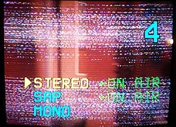
Alternately, you can perform a similar test if the noise pattern is visible on a TV set. The noise occurs in two horizontal groups or bands. Typically these two bands drift slowly upward on the screen. One group is a result of arcing during the positive half of the 60 Hz sine wave. The other group is a result from the negative half of the sine wave.
Note: The slow drift upward is caused by a slight difference in the power-line noise burst rate and the rate at which the TV images are transmitted. The TV images are transmitted at a rate of 59.94 Hz. This is because when television was first developed, a 60 Hz vertical scan frequency was selected so that any power-line noise would remain stationary on the screen, and be less annoying. When the color burst signal was added some years later, the scan frequency had to change to accommodate the color burst signal. Power-line noise occurs at 120 bursts per second. Since the power-line noise burst rate is almost twice the TV rate, two synchronized bands of noise appear on the screen. The slight difference in frequency causes these two bands to slowly drift upward on a TV screen.
It is usually best to perform this test at the lower VHF TV channels and with an antenna (as opposed to a cable hook-up). In addition, the positive and negative power-line noise burst may also have slightly different characteristics. This can cause each half of the cycle to have a slightly different pattern on the screen. As you turn the channel selector to higher frequency channels, the interference should diminish. If the interference can be observed on UHF channels, the source is probably relatively close by. See Figure 4.
What to Look For
As previously discussed in Section 1, corona typically does not cause radio noise. Radio noise is almost always caused by a spark or arc across an air gap. (There are also many other non-arcing sources, such as lights.) Any voltage across an air gap can cause radio noise -- even ground wires, neutral wires and wires not directly connected to a power-line.
Typical culprits include broken or loose hardware such as bolts on wood cross arm brackets, a broken lightning arrestor lead wire, inadequate hardware spacing such as a gap between a ground wire and a metal staple, metal tags left on hardware, or metal objects thrown on the power-line. Any metal parts that are not well insulated from, or well connected to, one another may form a spark gap. See Figure 5. We'll discuss more of the specifics later the next section.
Figures 3 - 5
-
 Figure 3
-
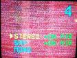 Figure 4a
-
 Figure 4b
-
 Figure 4c


V. How to Locate Power-Line Noise (By Mike Martin, RFI Sevices)
Locating power-line noise quickly is crucial to solving these problems in an economic and timely fashion. Mike Martin, an interference investigator for RFI Services, has twenty-five years of experience in the business of tracking and handling power-line noise complaints. Mike now shares some of his interference locating secrets with us.
An Overview
Once we receive an RTVI (Radio and Television) complaint form, we'll proceed to the complainant's neighborhood. We then track down each of the power-line interference sources we find in the neighborhood. We'll typically find several sources and list them on a repair request and send it to the line department for repairs.
Sound familiar? If so, your process of locating & dealing with power-line generated (RTVI) problems is similar to over 75% of the power companies with which I work. As you've probably already discovered with this technique, the process of locating RTVI sources can be extremely expensive if not handled correctly.
Here's a quick pop quiz. During a 24-hour day, there is only one time to investigate an interference complaint. Know what it is? If not - read on. My goal is to provide you with the basics for a sound and economic approach to resolving interference issues. I'll be answering this question and a lot more during the remainder of this section.
The First Step
First, all on-site investigations begin the same way - eliminate the possibility that the interference source is located in the complainant's residence. The majority of power company RTVI complaints I investigate are actually caused by equipment inside a customer's residence. Since interference gets worse as you get closer to the source, it makes sense to start your investigation with the complainant. (If the source was closer to someone else they would most likely be complaining.)
Fortunately, as we previously discussed, eliminating a particular residence or locating an inside source is a very easy process. It's simple enough that many complainants can actually perform this test as a prelude to the formal RFI investigation and without your utility's involvement. For your convenience, a simple step-by-step procedure handout, plus instructions for "locating inside sources" and "locating the residence" can be downloaded from www.rfiservices.com. This information is similar to the initial power-line noise test we discussed in the previous section. Providing it to your complainant as a first step can reduce your on site investigations by as much as 65%.
Let's now consider a case in which the customer is unable to perform this initial test -- or you've determined the interference source is external to his residence. A site investigation is obviously required. Again, start with the initial test as a first step. Even in cases where the customer has already performed this procedure, it's always a good idea to verify his results.
Once you've eliminated the possibility of an internal noise source, always start the RTVI locating process with the customer's equipment each and every time it is investigated. Whether it is a television interference (TVI) or radio frequency interference (RFI) complaint, always start by monitoring the customer's equipment while the problem is active. It is difficult, if not impossible to locate an RTVI source that doesn't exist. When you arrive at interference site, always view the problem as experienced by the customer with his or her equipment.
Finding The Source
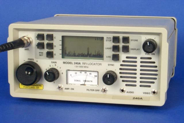
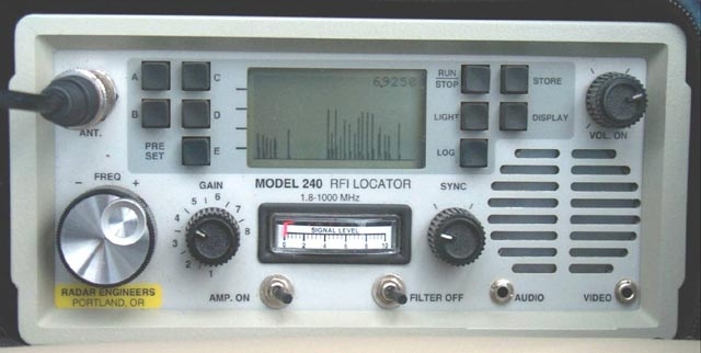
Once you've confirmed the problem is active we're ready for the next step -- locating the source. Attach our Defect Direction Finder (DDF) receiver to the customer's antenna. See Figure 6. This specialized equipment will enable us to monitor the symptoms as received by the customer's antenna. Our DDF setup should include a broadband AM receiver that covers the frequency range affected by the problem, an oscilloscope (scope) and an attenuator or RF gain control to adjust the RF signal level. With these tools we'll be able to monitor the sound and pattern produced by the RTVI source(s).
As an example, let's now consider a TVI complaint on television channel 4. While viewing channel 4 on the customer's TV, we should see dots and lines in two horizontal groups slowly moving upward on the screen. As one group goes out of view at the top of the screen a second group re-appears at the bottom. (This characteristic of power-line noise has already been previously discussed in this section.) Tune to 67.25 MHz, the frequency of channel 4, with our DDF receiver. We should now be able to view the noise as displayed on our scope and observe it's unique noise signature.
Scope patterns show many important facts about the source(s) affecting the customer's equipment. They can reveal the number of simultaneous sources, determine which source is the strongest, and even provide an indication as to the size of gap across which the spark is occurring. When working with TVI complaints, the scope can show which source is having the most impact on the TV picture. Don't be intimidated by this instrument. It is a very powerful tool and a simple process to use. Once it is set up, a scope rarely needs adjustment.
The Signature or Fingerprint Method
Each sparking interference source exhibits a unique pattern. By comparing the characteristics between the pattern taken at the customer's residence with those we find in the field, we can now determine which is an offending source from the many sources we might encounter. It therefore isn't surprising that a pattern's unique characteristic is often called its "fingerprint" or "signature." See Figure 7 for an example.
This is a very powerful technique and a real money saver. Even though you may encounter several different noise sources in the field, this method helps identify the sources are actually causing the interference problem. You need only correct the problem(s) matching the pattern affecting the customer's equipment. You can accomplish this method one of three ways:
- Record the pattern on the scope by drawing it on a note pad.
- Take a photograph of the pattern. You can then compare it to patterns found in the field.
- Or, use a receiver with a built in scope and the ability to store the pattern. This is the most modern method.
Interference locating receivers, such as the Radar Engineers Model 240 previously shown in Figure 6, have a built in oscilloscope display and waveform memory. They are ideal for the third method described in the previous paragraph. This is now the preferred method used by professional interference investigators. It provides the ability to toggle between the pattern saved at the customer's house and those from sources located in the field.
Once armed with the customer's noise fingerprint, you are ready to begin the hunt. Start your search in front of the customer's residence. Next, travel in a circular pattern around the customer's house, block-by-block, street-by-street, until you find the noise pattern matching the one recorded at the customer's house. Use VHF or UHF if you can hear the RFI at these frequencies. The longer wavelengths associated with the AM Broadcast Band, and even HF, can create misleading "hotspots" along a line when searching for a noise source. At these frequencies, you may find that the noise peaks at certain poles with different types of hardware mounted on them. As a general rule, only use the lower frequencies when you are too far away from the source to hear the offending RFI at VHF or UHF. Work at the highest frequency on which the noise can be heard. As you approach the source, keep increasing the frequency. See Figure 8.
By now you're probably beginning to see the value of having the correct equipment. Once you've matched the pattern obtained at the customer's house with one in the field, you're well on your way to locating the structure containing the source. The process now gets a bit interesting, but let's first go back for a moment and change the scenario a bit.
An Amateur Radio Complaint
Recall that the original complaint was TVI on channel 4. In this case we tuned our DDF locator to the frequency of channel 4. Let's now consider a complaint from an amateur radio operator with RFI at 21.4 MHz. The rules are still pretty much the same as with the TVI complaint:
- The source must be active at the time of our investigation.
- As always, observe the symptoms on the customer's equipment.
- Start the investigation by verifying the source is not located in the customer's residence.
- Connect the DDF receiver to the customer's antenna before investigating the area outside his house.
In this example however, tune the DDF receiver (while connected to the customer's radio antenna) for a frequency of 21.4 MHz. Again, observe and record the noise pattern for future viewing. Once ready to begin the hunt, start traveling in a circular pattern away from the customer's house until you find the matching noise fingerprint. If however the customer has a rotating antenna, use it to your advantage. Determine the direction of the noise source from the customer's house and reduce travel to a minimum.
Whether the complaint is TVI or RFI, a rotating antenna is always helpful. Instead of traveling in spiral away from the house to find the noise, you can reduce your search to only one direction. You need now travel only in this direction toward the source. Obviously, you can ignore any noise patterns that don't match our recorded fingerprint and concern yourself only with the offending source(s).
Another important clue can be obtained by tuning the DDF receiver up in frequency. Listen to the noise at VHF and UHF and make note of the frequency at which it starts to diminish. This frequency can provide an important clue as to the proximity of the source. The closer the source, the higher in frequency you can receive it. If the noise can be heard at 440 MHz, you can expect it to be relatively close by -- perhaps within less than a quarter mile radius. If it diminishes around 4 MHz, however, the source can be over a mile away.
An Important Rule
By now you can easily see a tremendous improvement in our noise locating efficiency. We can now quickly locate the direction of an interfering signal and match its pattern with any number of suspect noise sources. Using this fingerprint technique, we can more easily locate the structure containing the source.
Perhaps the most difficult hurdle to overcome in this process is to ignore those noises not affecting the customer's equipment. Whenever a suspect noise pattern doesn't match the recorded one, you must ignore it. Whenever attempting to locate the source of an interference complaint, you may encounter many power-line sources and other interfering signals. This is normal and to be expected. If however you were to repair all of them, the task of locating and solving RTVI complaints would become more difficult. As a result, the repair cost would quickly become unacceptable. An important rule for efficient and economic RFI troubleshooting is to locate and repair only the source causing the complaint.
During the Hunt
Let's now pick up where we left off a few paragraphs ago -- on the trail of an interference source. Thanks to the customer's beam antenna, we had a good idea of the direction to start the hunt. We started out heading in the direction from which the antenna indicated the noise was the strongest. This cut our travel distance down considerably since we didn't need to travel in a spiraling path away from the complainant's house. After a few blocks, we start receiving a noise with the same exact pattern as the one we recorded at the complainant's house. Let's now determine the actual structure containing the source.
At this point we want to reduce our signal level on our DDF receiver. We can do this in one of two ways. Typically, in most cases with a modern DDF receiver, simply turn the RF gain control down to the point we can achieve a minimum signal level (as indicated by the receiver's signal strength meter) and still have a clear noise pattern on the scope. If the receiver does not have an RF Gain control, an attenuator between the antenna and receiver can be used to reduce the signal level at the receiver's input.
We'll know if and when we are approaching the noise source by observing its signal strength during the hunt. The pattern amplitude increases as the signal gets stronger and we get closer. Alternately, if we find the signal getting weaker, we'll know we are going the wrong way and may lose the signal.
One secret to effective Defect Direction Finding is to maintain proper signal levels at the receiver. As indicated previously, we control this level by either an RF Gain control or an attenuator. Always maintain the minimum signal level necessary to observe the signal. As we approach the source, the signal level will increase. We must continuously adjust the gain to accommodate changes in the signal level. The importance of this rule cannot be overstated. Improper gain settings can make it extremely difficult to determine the direction of the source. In extreme cases, weaker signals may no longer be detected and stronger signals can produce abnormally high noise levels.
As we previously discussed, always ignore those patterns not consistent with the customer's complaint. As you approach the source and reduce your gain, the number of sources you want to ignore will decrease due to the receiver's reduced sensitivity. The receiver will no longer be able to hear weaker signals. Always maintain the lowest level possible when viewing noise signal patterns.
Directional Antennas
As previously discussed, the process is much easier when starting with a directional antenna at the customer's house. You can also use this same method while on the street. With an omni directional or whip antenna, you must move the vehicle to determine the direction of the higher signal level. If we use a handheld or vehicle mounted Yagi (directional) antenna, we can follow the direction of the strongest signal to the noise source. This will greatly reduce the amount of time and travel distance required during the hunt.
Radio Direction Finding (RDF) techniques typically offer the best and most efficient approach to locating most power-line noise sources. It is often the primary method of choice used by professionals. A hand-held Yagi works at VHF and UHF but must be used within its specified frequency range. Not only are VHF and UHF antennas typically smaller but also direction headings are more reliable. An attenuator is required between the antenna and the receiver if the receiver does not have one. Use as much attenuation as you can in order to minimize the area of search. As before - you'll need to add more and more attenuation as you approach the source. See Figure 9.
Pinpointing The Source
Once you know the structure containing the offending noise source, the next step is obvious. You must find the source on that structure. The RFI investigator, even if not a lineman must be able to pinpoint the source on the structure down to a component level from the ground. Alternately, an investigator can instruct the lineman on the use of a hot stick mounted device used to find the source. Regardless of your particular situation, both methods are similar.
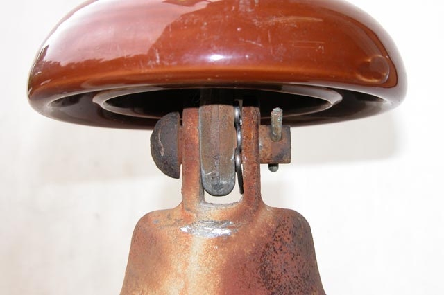
The key to success, just as with locating the structure, is the gain control. Hot stick mounted locators and the tools used from the ground can work very well provided you maintain minimum gain after initially detecting the noise. If the source appears to be at more than one location on the structure, reduce the gain. In part, this will eliminate any weaker noise signals from hardware not causing the problem. See Figure 10.
An ultrasonic dish is a useful tool for pinpointing the source of an arc. While no hot stick is required, an unobstructed direct line-of-sight path is required between the arc and the dish. This is not a suitable tool for locating the structure containing the source. It is only useful for pinpointing a source once it has been highly localized. An ultrasonic dish, for example, is not useful for locating the pole on which a noise source is located. It is however ideally suited for pinpointing the arcing hardware once the offending pole has been isolated. See Figure 11.
Common Sources
The following list contains some of the more common power-line noise sources I've encountered over the years. They're listed in order from most common to least common. Note that some of the most common sources (listed first) are not connected to a primary conductor. This in part is due to the care most utilities take to insure sufficient primary conductor clearance from surrounding hardware:
- Loose staples on ground conductor
- Loose pole top pin
- Ground conductor touching nearby hardware
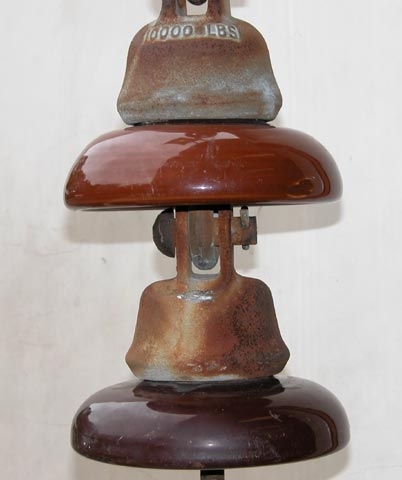
- Corroded slack span insulators
- Guy touching neutral
- Loose hardware
- Bare tie wire used with insulated conductor
- Insulated tie wire on bare conductor
- Loose cross arm braces
- Lightning arrestors
A Common "Non-Source"
Note that transformers don't even receive honorable mention in the list of most common power-line noise culprits. Despite their reputation, only a very small percentage of transformers are actually found to be the cause of an RTVI complaint.
Why are they blamed so often for noise they do not actually cause? Let's take a closer look at a typical scenario for some insight:
A customer calls with an RTVI complaint. He'll typically say he has looked long and hard for the cause the problem. He'll also add that he found the source on a transformer pole and that he believes the cause is the transformer. When power company investigator comes to start his investigation, like the customer, he finds the highest level to be at that pole. He too may then conclude the problem is the transformer. The transformer is changed and the problem is gone. Problem solved!
You may now ask the obvious question, "If the transformer wasn't the source, why is the noise gone? The actual reason may be that the source was only loose hardware. The hardware was tightened when the transformer is replaced. Obviously, it is far more economical to only tighten the loose hardware and not change the transformer. There is also added hardware associated with the transformer pole. Remember, the pole will have a driven ground conductor, lightning arrestor, often a down guy and other hardware that can act as an antenna and radiate noise. This can cause a high level of noise that fools the investigator into believing he has found the source structure. He hasn't found the source of the noise, only a better antenna to radiate it.
The Final Step
After you have successfully located and repaired the source, always check back with the customer to verify the complaint has been entirely solved. You may need to check for additional sources. If necessary, repeat this process until all the sources are corrected.
Some Final Tips and Comments
Let's now review and highlight some of the key points we've discussed in this section.
- Always visit the customer before an RTVI investigation.
- Always eliminate the complainant's residence first.
- Maintain minimum receiver gain once you've detected the offending noise pattern.
- If the noise appears to be coming from more than one source or direction, reduce the receiver's RF gain.
- Ignore any noise patterns not seen by the customer's antenna.
- Locate and repair only the source causing the complaint.
- Every antenna works best at one frequency. Use that frequency when using that antenna.
Equipment
By now you may be wondering about some of the DDF equipment we've discussed. Let's take a look at some professional grade instruments that might be used in a typical noise-locating arsenal:
Receiver
A good DDF receiver should be broadband and cover the AM broadcast band through at least 250 MHz and operate in the AM mode throughout this entire range. In addition, it must have an attenuator or RF gain control, and signal strength meter or indicator and preferably the option of battery power. The Radar Engineers Model 240 receiver was previously shown in Figure 6.
Antennas
You'll want several antennas to complete your DDF arsenal:
- A 7 MHz or lower frequency amateur radio antenna. This will help narrow down the area of sources that affect the AM Broadcast band as well as the lower amateur radio band frequencies. Such antennas are readily available from Amateur Radio suppliers. They are used for mobile HF operation and can be easily mounted on a vehicle with a multi-magnet base. See Figure 12.
- A 140 MHz-150 MHz or higher whip antenna used to locate the source structure. This antenna can be easily installed on a vehicle with a magnet base for this purpose. While this antenna does not have directional capabilities, you can use it for monitoring relative signal strength as you approach the source. See Figure 13.
- A directional Yagi type antenna. This antenna provides the capability to determine the direction of a noise source. Because it is larger and must be rotated, this is not an antenna that can easily be mounted on a vehicle. It can however be hand carried. Look for a directional Yagi antenna suitable that covers a frequency or frequency range somewhere between 140 and 500 MHz. See Figure 14.
Ultrasonic Dish
My ultrasonic receiver/pin pointer is great for pinpointing a noise source from the ground, once the structure it's on is located. Even though takes some experience to discriminate between corona and sparking sources, I wouldn't leave the office without one. See Figure 15.
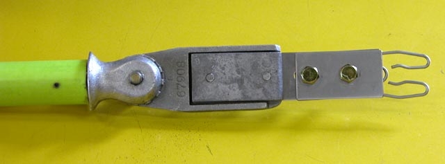
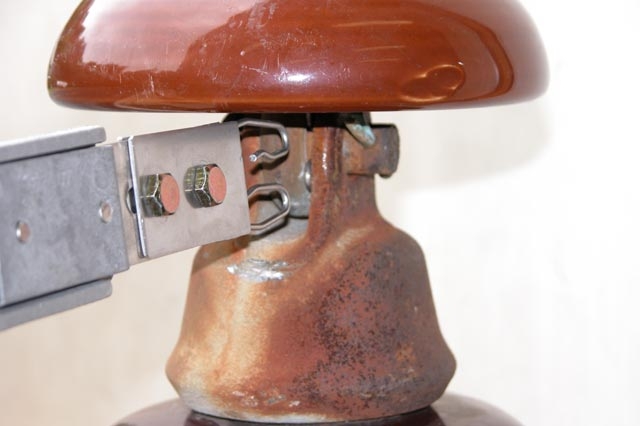
Hot Stick Sniffer
A hot stick mounted sniffer is "indispensable" to say the least. This is one tool without a substitute. It can be used to locate all power-line noise sources once the structure on which they are located is known. See Figure16.
Equipment of Minimal or No Defect Direction Finding Value
Thermal/ Infrared detectors and corona cameras are not recommended for the sole purpose of locating RTVI sources. It is rare that an RTVI source is detectable using infrared. In some cases, thermal vision and corona camera techniques can actually cause RTVI. These are not useful tools for locating power-line noise.
Answer to Pop Quiz
We've now covered a lot of ground in this section. I hope I've been able to provide you with some insight as to how better handle interference complaints in an economical, effective and timely manner. Have you been thinking about the answer to the pop quiz at the start of this section? By now you may think you know the answer.
Answer: When it's active.
And now let me end with this final and important comment:
Remember to always visit the customer first. Be sure to view the symptoms before locating sources in the field that may not be related to the complaint.
Figures 6 - 16
-
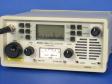 Figure 6
-
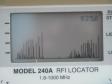 Figure 7A.
-
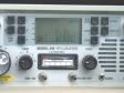 Figure 7B.
-
 Figure 8.


VI How to Fix (By Jody Boucher, Northeast Utilities)
Power-line RFI repairs typically involve eliminating an arc of some type. As we discussed previously, the arc occurs in an air gap located between two conductors on a pole or other source on the structure. The conductor materials can be wood, metal, dirty insulators -- just about anything that can conduct electricity -- and not necessarily a primary conductor. Arcs can occur for several reasons, including loose hardware, a cracked insulator, tracking, corrosion between two pieces of metal, or a loose tie wire. Since a difference in potential across a gap creates the arc, it stands to reason that eliminating the gap can repair most power-line RFI problems.
Once a noise source is located, a solution must be determined. The question of "what exactly needs to be done' may require some good judgment on the part of the troubleshooter. Obviously a line crew must go to the site and make some sort of repair. But what repair or replacement? This decision is typically based on a number of factors. How much work is involved? How many poles require attention? Is this an isolated or widespread problem? Has equipment deteriorated to a point that it needs to be replaced? Good judgment is essential for an effective and economical repair. Sound decisions will always help determine the best course of action to initiate a cure. A simple job of tightening loose hardware vs. an equipment replacement must be considered carefully when examining the possible options.
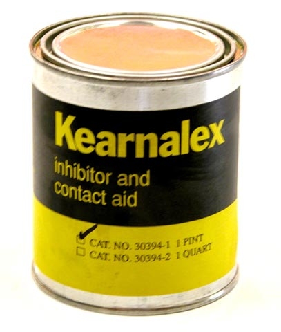
One popular option for a simple fix is a grease compound. The grease is applied to the offending gap in order to bridge it. Be cautious however. Grease may be only a temporary fix. Unless a suitable product has been correctly applied to the offending gap, it may eventually diminish in the elements or wash out by rain. The problem can then re-occur. In either case however, grease can be a temporary fix until a long-term solution can be initiated. See Figure 17.
Long-term repairs eliminate the gap by replacing the offending part, tightening hardware, or by cleaning to prevent tracking. Freezing and thawing can cause hardware to loosen, especially in colder climates. Helical spring washers added to the bolts can absorb the expansion and contraction of wood poles and maintain hardware tension to prevent gaps from forming.
In some cases, it may be better to replace an insulator with a modern polymer unit tie instead of re-tying the old one. The new design does not require a wire. It also eliminates the possibility the problem could reoccur in addition to a second and costly visit by a line crew. The line crew and truck are by far the most expensive part of power-line noise repairs. In most cases, the cost of replacement parts is only a small fraction of the total expenditure. Also, jobs written as a capital replacement can possibly be charged at the utility rate base. Most maintenance budgets are tight these days so any chance to capitalize a project and upgrade the plant is an economical advantage.
New products and materials for line construction are constantly evolving in the industry. For example, polymer construction of various types of post top insulators, dead ends and fused cut outs provide higher Basic Insulation Level (BIL), lighter weight and are less prone to stress cracks. Vice top polymer insulators are far superior to wire ties that can arc when loose, especially in cases involving Poly covered wire (commonly used in the northeast United States). See Figure 18.
The most cost effective repair is a single repair done only once. Getting it right the first time not only helps maintain customer satisfaction, it's essential for an economic problem solving. Replace versus repair of offending equipment often depends on the balance between a repair's level of difficulty and economic justification of its unit cost. Complete replacement for older, obsolete or damaged equipment may be a better choice.
Figures 17-18D
-
 Figure 17
-
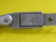 Figure 18A
-
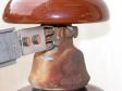 Figure 18B
-
 Figure 18C
VII. Process Dealing With Customer (By Terry Rybak, automotive EMC engineer)
Once you have verified the problem to most likely be power-line noise, and that it is not coming from a source internal to the home, generate whatever paperwork is necessary to document and track work done on the customer's complaint. The importance of diplomacy in many of these cases cannot be overstated. Caution the customer to never attempt to climb or bang on utility poles or touch or pull on guy wires while attempting to help locate the noise.
As you might already suspect, the best approach toward solving these types of issues requires a well defined process. It is for example, important maintain an accurate log. Be sure to record any "help ticket numbers" that may be assigned to the complaint as well as names, dates and a brief description of each conversation you have with customers.
Who Is Responsible?
The electric utility is responsible for correcting only that noise generated by the equipment and hardware that it actually owns. In cases where a utility customer uses an appliance or device that generates noise, the operator of the device is responsible for fixing it, even if the noise is conducted and radiated by the power company's power-lines.
Electric utility companies are often blamed for and even victimized by noise they do not cause and are not responsible to fix. This can be especially true when a customer owned noise source generates noise similar in sound to true power-line noise. Light dimmers, for example, are often mistaken for power-line noise. Customer owned doorbell transformers are also notorious and often found to be the source of an RFI problem. The latter is an example of a serious defect that should be repaired. In many cases, power-line or electrical noise is the first indication of an electrical failure about to occur.
It is the utility's responsibility to locate a source of noise emanating from their equipment. Utilities however do not always possess the necessary expertise or equipment to locate sources of radio noise. As a practical matter, many hams have assisted their utility in locating noise sources. In some cases, this can help expedite a speedy resolution.
Be careful, however. Do not be misled into making unnecessary and costly repairs unless you are certain that you have identified the noise source causing the customer complaint. Do not make a guess if you don't know the cause.
Always close loop
When the noise problem is resolved, be certain to confirm that the customer is satisfied. A power-line noise complaint should always begin and end with the customer. It is also worthwhile to write a memorandum thanking all company personnel who were involved in resolving the complaint.
VIII The FCC (By Riley Hollingsworth, Special Counsel, Spectrum Enforcement Division, FCC Enforcement Bureau)
The FCC has the responsibility to require that utility companies rectify power-line related interference problems within a reasonable time if the interference is caused by faulty power utility equipment. Under FCC rules, most power-line and related equipment is classified as an "incidental radiator." This term is used to describe equipment that does not intentionally generate any radio-frequency energy, but that may create such energy as an incidental part of its intended operation.
Commission rules specifically related to this topic are as follows.
Title 47, CFR Section 15.5 General conditions of operation.
(b) Operation of an intentional, unintentional, or incidental radiator is subject to the conditions that no harmful interference is caused and that interference must be accepted that may be caused by the operation of an authorized radio station, by another intentional or unintentional radiator, by industrial, scientific and medical (ISM) equipment, or by an incidental radiator.
(c) The operator of the radio frequency device shall be required to cease operating the device upon notification by a Commission representative that the device is causing harmful interference. Operation shall not resume until the condition causing the harmful interference has been corrected.
Title 47, CFR Section 15.13 Incidental radiators.
Manufacturers of these devices shall employ good engineering practices to minimize the risk of harmful interference.
Title 47, CFR Section 15.15 General technical requirements.
(c) Parties responsible for equipment compliance should note that the limits specified in this part will not prevent harmful interference under all circumstances. Since the operators of Part 15 devices are required to cease operation should harmful interference occur to authorized users of the radio frequency spectrum, the parties responsible for equipment compliance are encouraged to employ the minimum field strength necessary for communications, to provide greater attenuation of unwanted emissions than required by these regulations, and to advise the user as to how to resolve harmful interference problems (for example, see Sec. 15.105(b)).
If the complainant has attempted unsuccessfully to work through the power company complaint resolution process and has been unable to get the problem solved, the matter will be reviewed by the Enforcement Bureau. The FCC prefers that those responsible for the proper operation of power-lines assume their responsibilities fairly. This means that the utility company should locate the source of any interference caused by its equipment, or work with the complainant to establish that it is not power company hardware or equipment, and make necessary corrections within a reasonable time if the company's own hardware is the source of the interference.
While the FCC has confidence that most utility companies are able to resolve these issues voluntarily, it is important to be aware that unresolved problems may be a violation of FCC rules and could result in a monetary forfeiture for each occurrence. The FCC encourages the parties to resolve problems without FCC intervention, but if necessary to facilitate resolution, the FCC will investigate possible rules violations and address appropriate remedies.
We expect the utility company to advise the complainant what steps it is taking to correct interference problems reported to it. The FCC expects that most cases can be resolved within 60 days of the time they are first reported to the utility company. If a power company is unable to resolve such problems within 60 days after contact from the FCC, it is expected to advise the Enforcement Bureau about the nature of the problem, the steps it is taking to resolve it and the estimated time in which those steps can be accomplished.
IX Other Sources of Help (By Mike Martin and Mike Gruber)
It is beyond the scope of this article to provide a complete comprehensive treatment of the subject matter. Consider it as the first step toward improving your approach toward power-line noise issues. Let's now take a look at some additional sources of help and information that may prove helpful to you.
Help From The ARRL
The American Radio Relay League (ARRL) is a national organization representing amateur radio operators. Because amateur radio operators, often referred to as "hams," can be seriously impacted by power-line noise, the ARRL has been instrumental in helping educate power utilities on how to best deal with the problem. The ARRL provides technical information in the form of books, articles, web site information and a CD.
See the Track and Solve Electrical Interference Page for more information.
Books of interest include:
- AC Power Interference Handbook
Particularly helpful since it is dedicated to the subject of finding and fixing power-line noise. It also features in-depth coverage of noise signature techniques. - The ARRL RFI Book
Practical Cures for Radio Frequency Interference. Step-by-step interference solutions covering telephones, power-lines, TVs computers, VHF intermod and more!
Links:
The Power-Line Noise FAQ Page
Your complete guide to understanding power-line noise and the ARRL / FCC Cooperative Agreement. Power-Line Noise Mitigation Handbook for Naval and Other Receiving SitesThe fastest way to get the information is to download the PDF file. It can then be printed, saved to disk or copied to a CD. If, for any reason, you are unable to download this file, a CD copy can be obtained by contacting the ARRL RFI Desk at rfi@arrl.org.
You can also contact the ARRL RFI Desk should you have any questions or require additional information at:
American Radio Relay League
RFI Desk
225 Main Street
Newington, CT 06111
Email: rfi@arrl.org
Tel: 860-594-0392
Help From RFI Services
Mike Martin owns and operates RFI Services, an RFI locating & consulting firm in Tracey's Landing, MD. He's been locating interference sources and training Power & Telecom companies full time for over 25 years. Mike typically solves an average of 500 interference complaints a year. He often helps test RFI locating equipment for manufacturers and recommends improvements.
Mike has received acknowledgments in publications including: AC Power Interference Handbook * AC Power Interference Manual * Power-Line Interference, A Practical Handbook * T&D Magazine and * The American Radio Relay League Journal. Mike is multi-licensed by the FCC and considered to be the most experienced Interference Investigator in the country.
For more information about RFI Services consulting or Workshops, visit www.rfiservices.com.
X Some Final Comments (By Mike Gruber, ARRL Laboratory)
I hope we've succeeded in providing you with some new and better insight into the problem of power-line noise. Most sources are relatively easy to find with a little practice. While we've provided you with some general guidelines and information, experience is often the best teacher. We hope this article, coupled with the additional resources we've discussed at RFI Services and the ARRL, will help guide you along that path. We wish you the best in locating and solving your power-line noise issues!
Technology >> Radio Frequency Interference (RFI) >> Power Line >> Power Line Noise


