Electromagnetic interference and the cable operator
Part 1
Among the more difficult problems faced by the cable TV industry are those caused by leakage or ingress. The effects of these problems are felt from the front-office staff that has to deal with the paperwork associated with all of the applicable regulations, to the maintenance personnel in the field dealing with subscriber picture quality. Leakage is a two-way phenomenon; when signals can get out, over-the-air signals can also get in. The result of the latter is a condition known as electromagnetic interference (EMI), radio-frequency interference (RFI), TV interference (TVI) or ingress. No matter what you call it, the ultimate translation is trouble.
Ingress by over-the-air signals can come from many sources. There are millions of regulated radio transmitters in the United States, belonging to utilities, municipalities, business users, Amateur Radio operators and military users, to name just a few.
In addition to these licensed sources of radio-frequency energy, there are even more sources of radio energy or noise. The FCC Part 15 regulations govern license-free transmitters used in walkie-talkies, garage-door openers, video games and modulators, the infamous VCR "Rabbit," and a rather long list of other unlicensed, low-power radio transmitters. Unintentional sources of noise include computer equipment, microprocessor circuits used in consumer electronics equipment or security-alarm systems, motors, neon signs, thermostats, touch-to-switch lamps, the electrical-power distribution system and even street lighting. (Newer street lamps can be radio-frequency powered.)
The interference problems that affect cable TV operation are primarily manifested as interference to the subscriber's TV reception. Cable systems make use of spectrum allocated to over-the-air services, relying on the inherent shielding of coaxial cable to allow cable operators to use spectrum assigned to broadcasting and other users. It must be stressed that FCC regulations require that a cable operator must not cause interference to the licensed users of this spectrum. When the shield integrity is compromised, in addition to the problems associated with egress, the result can be interference and an unhappy subscriber. The resultant service costs (or a lost subscriber) represent a financial loss to the cable operator.
The examples and FCC regulations cited in this article are specifically applicable to the Amateur Radio Service, and cable TV interference (CATVI) resulting from amateur operation. However, the principles discussed and the steps described are applicable to nearly any interference problem resulting from cable
TV ingress. The FCC regulations that -govern Amateur Radio have provisions that help control interference; all radio services have similar regulations.
DEFINITIONS
Amateur Radio Service, FCC Part 97 regulations govern the Amateur Radio Service. They essentially define Amateur Radio operation as a non-commercial service comprised of people interested in radio operation and technology. The governments of the world have encouraged the growth of Amateur Radio because of the various forms of public service performed by hams. They provide message handling in times of disaster, and continuing contributions to electronics and radio technology.
An amateur is often "amateur" only by title. Many hams are professionals in the electronics industry. (Yes, the cable industry has more than its share of hams. Communications Technology regularly runs a column entitled "Hams in Cable TV." ) Even amateurs in relatively "low-tech" occupations had to pass a highly technical examination to get their licenses. For example, the Amateur Extra Class examination is roughly equivalent to the test for the FCC commercial radiotelephone license.
Interference. The term "interference" should be defined without emotion. To some people, it implies action and intent. The statement, "You are interfering with my television" sounds like an outright accusation. It is better to define interference as any unwanted interaction between electronic systems--period! No fault. No blame. It's just a condition.
RESPONSIBILITIES
Each person involved in an interference problem has individual needs, a unique perspective and a varying degree of understanding of the technical and personal issues involved. On the other hand, each of them may have certain responsibilities toward the other, and should be prepared to address those responsibilities fairly.
The transmitter operator is responsible for the proper operation of the radio station. If the transmitting equipment is emitting out-of-band signals, the operator must take the necessary steps to ensure that the station is in compliance with FCC regulations. The operator also should cooperate with the subscriber and cable company repair staff to find a resolution to the problem. It may be necessary for the operator to participate in the tests to help them find and correct the fault. The cable company's repair crew will work in close cooperation with the radio transmitter operator.
The subscriber should extend the same cooperation. An interference problem can only be corrected at its source. If, for example, interference is due to leakage in the wiring located in the subscriber's home or in the subscriber's TV receiver, asking the transmitter operator to correct the problem by making changes to the radio station will not result in a cure. The cable company's repair crew may need access to a subscriber's home or want to try some interference filters on the input cable to the subscriber's TV receiver or VCR. The subscriber should help in every reasonable way possible.
The cable company must ensure that the cable system is in proper working order. Beyond that, most cable operators are willing to help a customer resolve a problem concerning the quality of the received service. It is costly to leave an interference problem unresolved. Dissatisfied viewers can cancel their subscriptions and, if the interference problem is caused by a cable system leak, the FCC can levy fines or shut down channels.
Consumer electronic equipment manufacturers also share in the responsibilities. In 1982, Public Law 97-259 became law. Among other things, this legislation gave the FCC the authority to regulate consumer electronic equipment susceptibility. The FCC chose to implement a program of voluntary immunity standards and allow the manufacturers to devise a program of voluntary compliance. The American National Standards Institute (ANSI) has accredited standards for TV sets and VCRs that do provide a fair degree of immunity.
SOME ELECTROMAGNETIC COMPATIBILITY (EMC) FUNDAMENTALS
The non-technical side--diplomacy. There are occasional misunderstandings between the cable subscriber, the cable company services personnel and the transmitter operator who is involved in the problem. The subscriber often feels that the transmitter is to blame. After all, if the radio transmitter wasn't on the air, there wouldn't be a problem. The station operator often feels that the problem is always the responsibility of the cable company, and that it can always be fixed if the cable system shielding is improved. The cable company repair personnel are often stuck in the middle.
This scenario is sometimes compounded by hostility, hurt feelings and a hostile posture adopted by everyone who is involved. This creates an atmosphere in which the problem cannot be solved. At this point, the subscriber, the ham and, if necessary, the cable company staff must decide to put aside bad feelings and approach the situation with an open mind.
Technical. There are three components to any interference problem: (1) a source of radio-frequency energy or electrical noise, (2) a piece of susceptible equipment and (3) a path over which the unwanted energy is propagated. Any solution to an interference problem is going to involve a change made to one or more of these three factors.
In most cases of cable systems ingress, the source is difficult to control. If the source is a transmitter of a licensed radio service (this includes Amateur Radio, among many others) operating in compliance with the appropriate regulations, there may be little justification to ask the operator to make any changes to the station. Under some circumstances, however, it may be possible to improve the situation by making changes to the source. Ensure that the transmitting station is installed and operated using good engineering practice. The equipment should be properly grounded and installed so that the transmitted signal is coming from the antenna, not the transmitter chassis or ground. Transmitter output power and the proximity of the antenna to the susceptible equipment or the cable distribution system can all affect the severity of an interference problem.
There is little that can be done by the cable repair personnel to improve susceptible equipment. Most states have laws and licensing requirements that regulate the electronic equipment repair industry. In addition, most cable companies have policies that prohibit the cable company service staff from repairing or modifying any subscriber-owned equipment. The best source of help with susceptible equipment is the equipment's manufacturer.
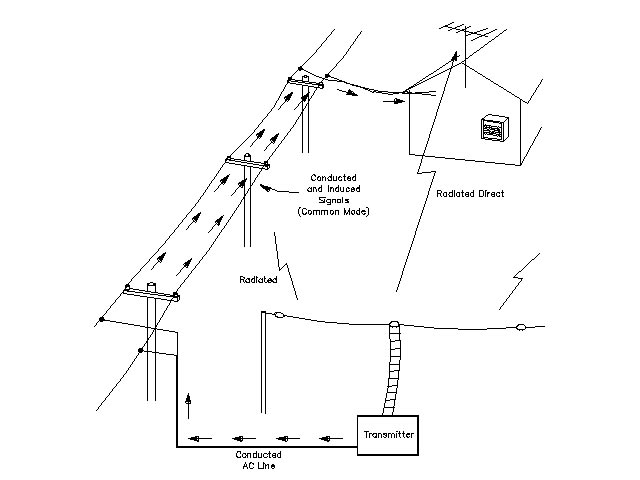
Figure 7.8--Conducted and direct interference. |
Interference can propagate via several different possible paths. Take a look at Figure 7.8. In the direct path, the interfering signal travels directly from the transmitting station's antenna to the susceptible equipment. Conducted interference travels from the source to the susceptible equipment by wires. Most of the time, however, the conducted signal is one that has been induced into the external or internal wiring of the susceptible equipment.
All electronic circuits require two wires (or their equivalents) - one wire for the signal to travel on and another for the signal return. In the differential mode a signal travels down the center conductor of a coaxial cable and uses the inside of the shield as its return path. In the common mode, the shield and center conductor act as if they were one wire, with the return path being earth ground (usually through the ac wiring). Figure 7.9 shows the difference between common-mode and differential-mode signals.
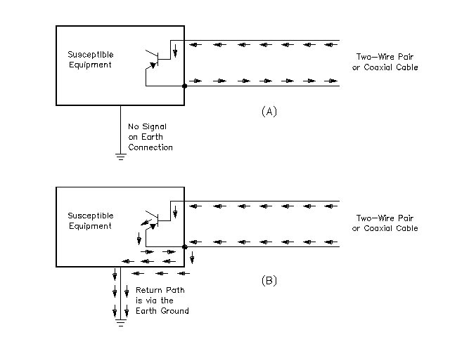
Figure 7.9--Differential (A) and common-mode (B) signals. |
Most signal-leakage cures will be applied to the path. The most important of these cures involve filtering and shielding. If a shield is placed between the source and the susceptible equipment, the effect of the interfering signal can be significantly reduced. Unfortunately, shielding is not a practical solution in most cases. It is difficult to imagine convincing a subscriber that the entire video system (including the viewers!) must be put into a grounded, shielded box.
Another means of affecting the path is the use of filters to attenuate unwanted energy. Part 2 of this article will discuss the practical steps that should be taken to cure interference problems, concentrating on the use of the necessary filters.
Electromagnetic interference and the cable operator - Part 2
Part 1 of this article appeared last month. It discussed the nature of the interference problem, ways to deal effectively with the subscriber and the radio operator, and electromagnetic compatibility technical fundamentals. It is time to outline some standard approaches that usually result in a solution to the problem.
The first technical step toward finding a solution to an interference problem is for the cable company service personnel to determine if there is any leakage in the cable system wiring. If the interfering radio signal is leaking in, it will, in most cases, be impossible to filter.
Fortunately (for troubleshooting purposes), if a signal is leaking in it others are leaking out. Cable operators have many good methods for measuring leakage, -although a passing cumulative leakage -index (CLI) figure on the Federal Communications Commission's Form 320 does not ensure that leakage and ingress are completely under control. Modern communications receivers have a lot more sensitivity than test conditions used by cable operators to find 20 mV/meter leaks.
The radio operator can do a quick check for leakage in the VHF ham bands by using a receiver designed for the Amateur Radio Service. ( A local ham can often be of help here.) If a strong carrier is heard in the subscriber's home on the frequency of the video carrier in the 144 or 222 MHz amateur bands, then leakage is indicated. (Editor's Note: Be aware that some poorly shielded TV sets, VCRs or FM tuners may be a source of leakage.) On the other hand, if no carrier is heard, then the cable system assuredly does not leak at that point. In some cases, it may be possible to hear a signal when the receiver's antenna is placed within inches of the cable. It may, however, be leaking elsewhere in the neighborhood and being delivered to the subscriber's drop. The accompanying table shows the frequencies of the video and sound carriers that can be found in, or adjacent to, the amateur bands.
Another effective way of evaluating leakage is to use a spectrum analyzer. Spectrum analyzers are usually well-shielded and filtered, and can be relied upon to measure only signals inside the cable. Under some conditions, an in-band, spurious signal that is 60 dB weaker than the video carrier can cause just-perceptible interference. If the in-channel radio transmitter's fundamental signal is weaker than this, then cable system leakage is not contributing to the problem, so other causes should be investigated.
Problem Channels for Amateur Radio Operators
|
CHECK THE CABLE SYSTEM THOROUGHLY
Many cases of ingress can be traced to something the subscriber has done. It is not rare for a subscriber to add additional cable and splitters to the installation to save monthly fees for additional outlets. It is not unheard of for subscribers to run cables to a neighbor's house, to give away free cable, or to take advantage of free cable (with or without the other party's consent). As if this weren't bad enough, this if often done using substandard cable, splitters or installation techniques (check the crimps). Even worse, they may use wires such as twin-lead or zip cord, or even hook up an external TV antenna in parallel with the cable. Even if the subscriber has done none of these things, substandard cables may have been substituted for the quality jumper cables used at the time of installation, or the subscriber may have repaired a broken connector using parts and techniques not up to industry standards. Look for these things --you may fix your problem without having to go any further.
All of these defects can result in severe leakage. Not only can they be the direct cause of the interference problem, but they can have quite the impact on your system's cumulative leakage performance. Some of them also represent a significant revenue loss.
THE SUSCEPTIBLE TV SET
In many cases the ingress is occurring in the subscriber's TV set or VCR. This should be tested early in the trouble-shooting process. Disconnect the TV set from the cable system and terminate its input with a 75 ohm terminator or 300 ohm carbon resistor (as appropriate for its input impedance). Select the channel the TV set is normally tuned to--usually Ch. 3 or 4 if a set-top converter or VCR is used to select channels. If the TV set is cable--compatible, select the channel that is most prone to interference. If the snowy raster is strongly affected when the interfering signal is present, this indicates that the TV set is susceptible to direct pickup. If the TV set tests okay, repeat the process for the VCR.
The cable operator is not responsible if the TV set or VCR is susceptible to direct pickup of the interfering signal. However, many operators want to offer some help to any subscriber who is having reception problems. If there is definitely no ingress, and these steps do not effect a cure, then the problem is in the subscriber-owned equipment. This equipment should only be fixed by the manufacturer or an authorized service facility. Have the subscriber contact the manufacturer through the address given for the Electronic Industries Association. The EIA maintains a data base of manufacturers and key electromagnetic compatibility (EMC) personnel.
THE RADIO TRANSMITTING STATION AND OPERATOR
Because a cable system is (in theory) a closed system, it really shouldn't matter if the radio station is transmitting harmonics or other out-of-band spurious emissions; the cable system is not supposed to respond to any over-the-air signals. However, it is helpful if the radio station can be demonstrated to be "clean," especially if the interference is only on channels harmonically related to the transmitted fundamental frequencies. If the station is not causing interference to an antenna-connected TV set located on the premises (often at home), this usually indicates that the transmitter is not transmitting any interfering out-of-band signals.
COOPERATION
As mentioned in Part 1, secure the cooperation of the transmitter operator. If the transmitter is an Amateur Radio station, you and the subscriber are lucky - it is in the spirit of the Amateur Radio Service to perform public service. As a public service, most amateurs will be willing to help with an interference problem, even if it doesn't involve their station. In any event, the station operator can help ensure that there is a signal on the air while the repair crew is at the subscriber's house; this will prevent the "no problem found" syndrome. The station operator can vary the station power, frequency and beam antenna headings (all within the limits of the station authorization) to help diagnose the cause of the problem.
SOME MORE TECHNICAL "FIRST STEPS"
Look around and investigate other causes. Although it is natural to think first of the local amateur or CB station with the 120-foot tower as the source of the interfering signal, there are many other potential sources of interference. Much time can be wasted blaming the local ham if the problem is being caused by a defective electrical system insulator on a near-by utility pole, or by a noisy appliance operating in the subscriber's own house.
Simplify the problem. Many cases of interference have several causes. If the subscriber has multiple outlets, many of which have VCRs, video games, A/B switches and TV receivers connected to stereo systems with long speaker leads and who-knows-what attached, it may be the interference is entering the system. Anything connected to the cable system--by any means-is suspect.
To begin troubleshooting such a complex system, completely disconnect everything except one outlet and one TV set and its set-top converter. (More about the set-top converter later.) When the following steps have been employed to reduce the interference to this simplified installation, start adding things back, one at a time, eliminating interference one step at a time. If all goes well, all of the interference will be eliminated. If not, at least the defective piece of susceptible equipment will have been identified. Most subscribers will realize that if one piece of equipment is interference-free and another is not, the equipment that is having the problem must be deficient in some way.
Testing
Figure 7.10 |
Determine which transmitted frequencies cause the problem. It may be possible to obtain this information from the radio station log book. If not, have the station operator transmit on each frequency band for which the station has equipment, observing any interference present. If the operator has been able to secure the help of another qualified operator - for an Amateur Radio operator this is usually the ARRL section technical coordinator (more on this very important person later in the article) -- they may be able to coordinate the testing using hand-held, two-way radios. If not, a telephone link between the subscriber's home and the station operator will help things to run smoothly.
If the interference results from medium-frequency (MF) or high-frequency (HF) operation (signals below 30 MHz), the solution to the problem may be as simple as the installation of a differential-mode, high-pass filter in the cable that feeds the set-top converter. Figure 7.10 shows one way to do this. Even if this filter doesn't cure the interference, leave it in place, at least for the time being. Caution: this filter is not compatible with most two-way systems. It will filter out all signals from 5 to 40 MHz!
TIME TO GET DOWN TO BRASS TACKS
There are a number of cable channels that can be affected by cable system ingress. These channels make use of over-the-air frequencies that are allocated to other services, often located immediately adjacent to amateur, business or pager frequencies. The table earlier in this article lists the frequencies for a standard system with no offsets. Many systems use offsets, or one of the other channel schemes.
If the interference results to Ch. E, Ch. J or Chs. UU through YY (Ch. 18, Ch. 23-24 or Ch. 57-61) from amateur VHF operation, it will not be possible to filter the undesired signal from inside the cable without affecting the desired TV signal as well. All is not lost however. Sometimes the TV receiver, VCR or set-top converter will exhibit a strong response to the common-mode signal present on the outside (shield) of the cable, or to a lesser extent the common-mode or differential-mode RF signals that may be present on the ac electrical system wiring. After all leaks have been repaired, it may be -possible to do something about these -signals.
THE COMMON-MODE FILTER
The common-mode filter or choke may be one of the best-kept secrets in the Western world. Ingress problems that are not caused by cable leakage are usually the result of the common-mode response of the TV receiver, the VCR or the set-top converter. This common-mode response usually can be cured with the use of a common-mode choke.
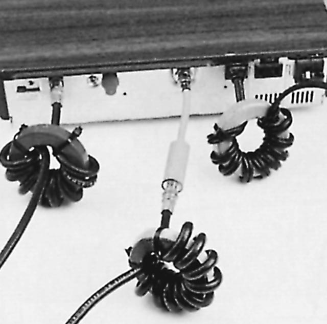
Figure 7.11 |
The simple cable TV installation shown in Figure 7.11 is virtually bulletproof. The placements of the cable and ac line common-mode filters have been chosen to minimize the amount of undesired common-mode energy reaching the set-top converter. Two different cable common-mode filters are shown in Figure 7.12. Do not substitute unsuitable ferrite materials for those specified in the description. As an example, it might be possible to scrounge some ferrite from an old TV set's deflection yoke, but the ferrite material used was designed to perform at 15.734 kHz. It may, or may not, work well at the frequency of the radio station.
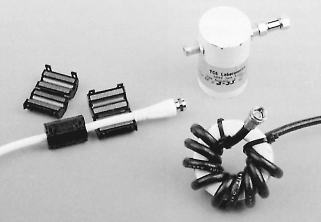
Figure 7.12 |
Common-mode filters for coaxial cable should be installed as close as possible to the cable input connector of the set-top converter, TV receiver or VCR. In extreme cases, it may be necessary to install a common-mode choke at each end of all interconnecting cables (VCR to TV set, for example) in the system.
AC LINE FILTERING
AC line common-mode choke. The undesired signal also can be coupled into the subscriber's equipment through the ac power lines. These lines can function as antennas. The signal that is induced into ac power lines can be either common- or differential-mode. Install a common-mode choke on the ac line cord of the TV set, as close as possible to the point where the cord enters the set. This choke should be made by wrapping 10 to 20 turns of the ac line cord through the ferrite toroid (or onto a ferrite rod). This will reduce any common-mode signal that has been picked up by the ac lines.
The ac line differential-mode filter. If the ac line common-mode choke doesn't help, add differential-mode ac line filter. The is the type of ac line filter commonly sold by electrical supply companies. (They also are sometimes called "brute force" ac line filters.) This filter should be installed as close as possible to the point where the ac line cord enters the TV set.
These "standard" cures will probably take care of 90% of the interference problems that plague your subscribers. But that other 10% can be the most difficult to pin down. Part 3 of this series discusses some of the more advanced troubleshooting techniques and cures, and lists several sources of help.
Electromagnetic interference and the cable operator - Part 3
It discussed the nature of the interference problem, ways to deal effectively with the subscriber and the radio operator, and electromagnetic compatibility technical fundamentals. Part 2 was in last month's issue. It discussed the common cures for cable TV interference. Now, we will pick up where we left off, delving into some troubleshooting techniques and cures.
All of the cures covered in last month's installment should result in an interference-free installation. However, if interference is still present, there may be a problem with direct pickup by the TV receiver, VCR or set-top converter. If any of these devices are tuned to the frequency of a local Amateur Radio signal (Ch. E, Ch. 18 in most cable systems, for amateur 144 to 148 MHz signals, for example), it should be the prime suspect. If ingress (and most likely leakage as well) is taking place inside the subscriber's TV set or VCR, there is almost nothing the cable company service personnel can do to cure the problem. The only source of help is the product manufacturer or electronic service personnel.
VCR--FRIEND OR FOE?
If it appears that the subscriber's cable-compatible TV set is the entry point for the ingress, the battle is not necessarily lost. Many subscribers have a VCR and, in some configurations, that VCR can be used as a channel selector. VCRs are often newer than the TV receiver, and they may have been designed to meet the ANSI immunity standards. They are often better shielded than the TV receiver. With the proper installation of cable common-mode chokes and the appropriate ac line filters, it may be possible to successfully use the VCR as a channel selector. In that case, the susceptible TV set will be tuned to a low VHF channel (usually Ch. 3 or 4). This makes it much less susceptible to interference than it was when it was tuned to the radio station's transmitted frequency. Unfortunately, in some cases, the VCR can be more susceptible than the TV set, or can exhibit intermodulation problems that only worsen in the presence of strong over-the-air signals.
Most set-top converters are well shielded, although they can be susceptible to interference from common-mode signals. If used in conjunction with cable and, if needed, ac line electrical chokes, they often can be used as a channel selector for a susceptible TV receiver. A fully filtered set-top converter can be used as a diagnostic tool. Keep one available for use when troubleshooting all cases of interference. It will help demonstrate to the subscriber that the problem originates from a susceptible piece of subscriber-owned equipment.
| Multiple Problems--A Case History
The ARRL Technical Department staff often gets letters or telephone calls about ham radio-related EMI. I recently received a telephone call from Chris Saunders, technical customer service manager for Cox Cable Greater Hartford, about a Ch. E ingress problem that was affecting one of the company's customers. They had thoroughly rewired the installation to correct a few identified leaks, but this did not completely fix the problem. Chris had heard about the help that can be supplied by the ARRL, so he gave me a call. He described the tests that had been performed by the cable repair crew. I agreed with his conclusion that the ingress was external to the cable system. In addition to my duties here at ARRL Headquarters, I also serve as an unpaid field volunteer Technical Specialist for the Hartford area. I explained to Chris that I would be willing to go over to the subscriber's house sometime and see what I could do. I made an appointment for a Sunday afternoon, and brought my survival kit with me--a collection of ferrite toroids, a few 75 W high-pass filters, 75 W terminators and some brute-force ac line filters. The subscriber met me at the door. He appeared to be quite friendly (what a relief!) and we sat down to talk a bit before I got down to "business." I explained that I was an Amateur Radio volunteer who was offering to help with a problem that involved a local amateur. He then pointed out the 100-foot tower on an adjacent piece of property. The Problem We then switched on his TV set to Ch. 18 (Ch. E). Within a few minutes, the screen was filled with a broad cross-hatch interference pattern that lasted about 20 seconds. This repeated randomly about every minute or so. I had brought a 144 to 148 MHz handi-talkie (H-T) transceiver with me, so I was able to transmit a signal that easily duplicated the interference. I also was able to quickly locate the other station on the air. It turned out that the station was an amateur repeater, set up to automatically rebroadcast the signals of hundreds of area amateurs to increase their service area. This explained the nearly non-stop nature of the interference. The subscriber had wondered how the ham was able to stay up and operate day and night! The Cox repair crew had previously replaced the drop and rewired the entire house. The subscriber told me that this made quite an improvement, but that the interference was still objectionable. (I agreed.) Because there had been an improvement, I knew that there had been a leak. I turned my H-T receiver to the Ch. E video carrier frequency. I could not hear any trace of the video carrier. This meant that the cable installation was clean. Good! I could now see if we could locate the point where the ingress was happening. The subscriber was using a cable-compatible TV set to select channels, in conjunction with a VCR. I followed my own advice and disconnected the VCR. We still had interference. I then tried common-mode chokes on the incoming cable, to no avail. A common-mode choke on the TV set's ac line cord seemed to make a small difference, but not enough to really fix the problem. It was beginning to look like the problem might be inside the TV set! I disconnected the TV set from the cable and put a 75 W terminator on the incoming cable and on the TV set input. I keyed the H-T transmitter. Uh, oh ... the screen went 100% black! This was not good news. The TV set was picking up the interfering signal directly. I explained how Connecticut state law (and common sense) prohibited me from trying to repair his TV set for him. The Hunch The subscriber had a hunch, though, that saved the day! He suggested that we try the VCR, just to see if the VCR might work properly now that the common-mode chokes were in place. It worked! It seems that the whole problem resulted from a multitude of causes, all of which had to be fixed before the problem was solved. Originally, there was a leakage problem, resulting in interference that couldn't be filtered when the 145-MHz amateur signal leaked into the cable. The TV receiver was subject to direct pickup of over-the-air signals, a problem for the manufacturer. The VCR was sensitive to the common-mode signal on the shield of the coaxial cable, but when the leak was fixed and the common- mode chokes were installed, the VCR was able to work properly. When the VCR was used as a channel selector, the susceptible TV set was tuned to Ch. 4 instead of Ch. 18, thus eliminating the problem. Most set-top converters are well shielded, and, if common-mode chokes are installed, they will usually perform properly in the presence of strong, over-the-air signals. Another happy customer (and a happy ham). A neighborhood dispute had been resolved. Information about the ARRL Technical Coordinator program is available from ARRL Headquarters. See "Useful addresses" in the "Sources of Information" sidebar. Write to our EMI specialist (currently that's me) here in Newington, CT. We are looking for the cable operator who wants to do something about EMI!--Ed Hare Sources of Information |
THE UNEXPECTED
Be prepared for the unexpected. The science of electromagnetic compatibility (EMC), although exact and predictable (in retrospect), is sometimes thought of as "black magic." Unexpected factors can sometimes come into play. It may take a specific combination of subscriber equipment hookups, or a combination of two or more transmitters being on the air simultaneously to cause the problem. In some cases, even the weather can be a factor. The ingress may only occur when the ingress point is wet (or dry, or hot, or...), which is an almost sure sign that the leak is outdoors. In complex cases like these it may take the services of an EMC expert, or a cable repair person who has been forced into that role!
| Sources of Information
The ARRL Headquarters staff has prepared EMC and RFI Web pages to help amateurs, consumers and utility companies win the battle against EMI. The ARRL Regulatory Information Branch also provides a Regulatory RFI Web Page that describes the rules and regulations that apply to interference problems involving amateurs. This page also includes a link to the FCC Interference Handbook. The technical department also provides an RFI / EMI Page dedicated to the technical and diplomatic aspects of interference problems. This page also includes a downloadable pamphlet for the consumer or neighbor of a ham that explains interference in non-technical terms. Additional links also provide information on parts suppliers for filters, ferrites and other EMI-control devices. References |
SOURCES OF HELP
Many cable companies have a regional or corporate engineer who can help with interference and leakage problems. He will certainly get involved if the problem escalates to a formal Federal Communications Commission interference complaint, so he would rather be informed early in the interference resolution process!
The station operator and service personnel are handy sources of help. If the station operator is a licensed radio amateur, the operator may have a good understanding of the applicable technical issues. Even if the radio amateur is not technically well-versed, ham help may be available. The ARRL has set up a system of technical volunteers to help with interference problems that involve the Amateur Radio Service. This system consists of the ARRL section technical coordinators (TC), their assistant technical specialists (TS) and possibly local amateur-club TVI (TV interference) or RFI committees. Many cable operators already have standing relationships and active interference resolution programs with local radio amateur clubs. These are usually coordinated through the ARRL section TC.
The amateur may know how to get in touch with the TC or local club interference committee. If not, the ARRL section manager for each section will be able to supply the address of the section technical coordinator. A listing of ARRL section managers is found on page 12 of any recent QST (the official journal of the ARRL). The ham probably has a copy. If not, ARRL headquarters will be able to supply the information.
These local volunteers are dedicated in every sense of the word. There will be no charge for their "services." The other side of that coin, however, is that there is a limit to what can be asked of them. It would not be appropriate for the amateur, the subscriber, or the cable company to make unrealistic demands upon any of these people. It only takes one 3 a.m. telephone call to ruin an otherwise fine relationship!
The June 1993 issue of Communications Technology lists hundreds of amateurs that are employed in the cable industry. This list is updated yearly by Steve Johnson, NØAYE, of Time Warner Cable, and is a "natural" resource for the cable operator. It may be possible to encourage any amateurs that work for your cable company to take an active role in local-club interference activities to act as a first line of defense against leakage and ingress.
SUMMARY
Cable TV interference problems can be solved. It takes a combination of diplomacy, expertise, perseverance and a -thorough approach to troubleshooting. Contact the ARRL for assistance with any difficult interference problems that -involve a radio amateur.
If you have any questions concerning the reproduction or distribution of this material, please contact: tis@arrl.org
ARTICLES
- CATV Leakage
Ron Hranac, N0IVN shares some thoughts on CATV leakage, and offers suggestions on the problem of CATV interference to 145.250 MHz.
- Deploying VOIP on the Outside Cable Plant
Ron Hranac, N0IVN, Cisco Systems -- This presentation, done by Ron for the cable industry, outlines the strict techncial standard to which cable plants must comply in order for VOIP to operate reliably. Ron is a member of the ARRL EMC Committee, advising ARRL on EMC matters related to the cable industry. (Note: click on the notes field near the bottom of the screen to see notes about many of the slides.)
Electromagnetic Interference And The Cable Operator
Ingress by over-the-air signals can come from many sources. There are millions of regulated radio transmitters in the United States, belonging to utilities, municipalities, business users, Amateur Radio operators and military users, to name just a few.
In addition to these licensed sources of radio-frequency energy, there are even more sources of radio energy or noise. The FCC Part 15 regulations govern license-free transmitters used in walkie-talkies, garage-door openers, video games and modulators, the infamous VCR "Rabbit," and a rather long list of other unlicensed, low-power radio transmitters. Unintentional sources of noise include computer equipment, microprocessor circuits used in consumer electronics equipment or security-alarm systems, motors, neon signs, thermostats, touch-to-switch lamps, the electrical-power distribution system and even street lighting. (Newer street lamps can be radio-frequency powered.)
The interference problems that affect cable TV operation are primarily manifested as interference to the subscriber's TV reception. Cable systems make use of spectrum allocated to over-the-air services, relying on the inherent shielding of coaxial cable to allow cable operators to use spectrum assigned to broadcasting and other users. It must be stressed that FCC regulations require that a cable operator must not cause interference to the licensed users of this spectrum. When the shield integrity is compromised, in addition to the problems associated with egress, the result can be interference and an unhappy subscriber. The resultant service costs (or a lost subscriber) represent a financial loss to the cable operator.
The examples and FCC regulations cited in this article are specifically applicable to the Amateur Radio Service, and cable TV interference (CATVI) resulting from amateur operation. However, the principles discussed and the steps described are applicable to nearly any interference problem resulting from cable
TV ingress. The FCC regulations that -govern Amateur Radio have provisions that help control interference; all radio services have similar regulations.
DEFINITIONS
Amateur Radio Service, FCC Part 97 regulations govern the Amateur Radio Service. They essentially define Amateur Radio operation as a non-commercial service comprised of people interested in radio operation and technology. The governments of the world have encouraged the growth of Amateur Radio because of the various forms of public service performed by hams. They provide message handling in times of disaster, and continuing contributions to electronics and radio technology.
An amateur is often "amateur" only by title. Many hams are professionals in the electronics industry. (Yes, the cable industry has more than its share of hams. Communications Technology regularly runs a column entitled "Hams in Cable TV." ) Even amateurs in relatively "low-tech" occupations had to pass a highly technical examination to get their licenses. For example, the Amateur Extra Class examination is roughly equivalent to the test for the FCC commercial radiotelephone license.
Interference. The term "interference" should be defined without emotion. To some people, it implies action and intent. The statement, "You are interfering with my television" sounds like an outright accusation. It is better to define interference as any unwanted interaction between electronic systems--period! No fault. No blame. It's just a condition.
RESPONSIBILITIES
Each person involved in an interference problem has individual needs, a unique perspective and a varying degree of understanding of the technical and personal issues involved. On the other hand, each of them may have certain responsibilities toward the other, and should be prepared to address those responsibilities fairly.
The transmitter operator is responsible for the proper operation of the radio station. If the transmitting equipment is emitting out-of-band signals, the operator must take the necessary steps to ensure that the station is in compliance with FCC regulations. The operator also should cooperate with the subscriber and cable company repair staff to find a resolution to the problem. It may be necessary for the operator to participate in the tests to help them find and correct the fault. The cable company's repair crew will work in close cooperation with the radio transmitter operator.
The subscriber should extend the same cooperation. An interference problem can only be corrected at its source. If, for example, interference is due to leakage in the wiring located in the subscriber's home or in the subscriber's TV receiver, asking the transmitter operator to correct the problem by making changes to the radio station will not result in a cure. The cable company's repair crew may need access to a subscriber's home or want to try some interference filters on the input cable to the subscriber's TV receiver or VCR. The subscriber should help in every reasonable way possible.
The cable company must ensure that the cable system is in proper working order. Beyond that, most cable operators are willing to help a customer resolve a problem concerning the quality of the received service. It is costly to leave an interference problem unresolved. Dissatisfied viewers can cancel their subscriptions and, if the interference problem is caused by a cable system leak, the FCC can levy fines or shut down channels.
Consumer electronic equipment manufacturers also share in the responsibilities. In 1982, Public Law 97-259 became law. Among other things, this legislation gave the FCC the authority to regulate consumer electronic equipment susceptibility. The FCC chose to implement a program of voluntary immunity standards and allow the manufacturers to devise a program of voluntary compliance. The American National Standards Institute (ANSI) has accredited standards for TV sets and VCRs that do provide a fair degree of immunity.
SOME ELECTROMAGNETIC COMPATIBILITY (EMC) FUNDAMENTALS
The non-technical side--diplomacy. There are occasional misunderstandings between the cable subscriber, the cable company services personnel and the transmitter operator who is involved in the problem. The subscriber often feels that the transmitter is to blame. After all, if the radio transmitter wasn't on the air, there wouldn't be a problem. The station operator often feels that the problem is always the responsibility of the cable company, and that it can always be fixed if the cable system shielding is improved. The cable company repair personnel are often stuck in the middle.
This scenario is sometimes compounded by hostility, hurt feelings and a hostile posture adopted by everyone who is involved. This creates an atmosphere in which the problem cannot be solved. At this point, the subscriber, the ham and, if necessary, the cable company staff must decide to put aside bad feelings and approach the situation with an open mind.
Technical. There are three components to any interference problem: (1) a source of radio-frequency energy or electrical noise, (2) a piece of susceptible equipment and (3) a path over which the unwanted energy is propagated. Any solution to an interference problem is going to involve a change made to one or more of these three factors.
In most cases of cable systems ingress, the source is difficult to control. If the source is a transmitter of a licensed radio service (this includes Amateur Radio, among many others) operating in compliance with the appropriate regulations, there may be little justification to ask the operator to make any changes to the station. Under some circumstances, however, it may be possible to improve the situation by making changes to the source. Ensure that the transmitting station is installed and operated using good engineering practice. The equipment should be properly grounded and installed so that the transmitted signal is coming from the antenna, not the transmitter chassis or ground. Transmitter output power and the proximity of the antenna to the susceptible equipment or the cable distribution system can all affect the severity of an interference problem.
There is little that can be done by the cable repair personnel to improve susceptible equipment. Most states have laws and licensing requirements that regulate the electronic equipment repair industry. In addition, most cable companies have policies that prohibit the cable company service staff from repairing or modifying any subscriber-owned equipment. The best source of help with susceptible equipment is the equipment's manufacturer.

Figure 7.8--Conducted and direct interference. |
Interference can propagate via several different possible paths. Take a look at Figure 7.8. In the direct path, the interfering signal travels directly from the transmitting station's antenna to the susceptible equipment. Conducted interference travels from the source to the susceptible equipment by wires. Most of the time, however, the conducted signal is one that has been induced into the external or internal wiring of the susceptible equipment.
All electronic circuits require two wires (or their equivalents) - one wire for the signal to travel on and another for the signal return. In the differential mode a signal travels down the center conductor of a coaxial cable and uses the inside of the shield as its return path. In the common mode, the shield and center conductor act as if they were one wire, with the return path being earth ground (usually through the ac wiring). Figure 7.9 shows the difference between common-mode and differential-mode signals.

Figure 7.9--Differential (A) and common-mode (B) signals. |
Most signal-leakage cures will be applied to the path. The most important of these cures involve filtering and shielding. If a shield is placed between the source and the susceptible equipment, the effect of the interfering signal can be significantly reduced. Unfortunately, shielding is not a practical solution in most cases. It is difficult to imagine convincing a subscriber that the entire video system (including the viewers!) must be put into a grounded, shielded box.
Another means of affecting the path is the use of filters to attenuate unwanted energy. Part 2 of this article will discuss the practical steps that should be taken to cure interference problems, concentrating on the use of the necessary filters.
Electromagnetic interference and the cable operator - Part 2
Part 1 of this article appeared last month. It discussed the nature of the interference problem, ways to deal effectively with the subscriber and the radio operator, and electromagnetic compatibility technical fundamentals. It is time to outline some standard approaches that usually result in a solution to the problem.
The first technical step toward finding a solution to an interference problem is for the cable company service personnel to determine if there is any leakage in the cable system wiring. If the interfering radio signal is leaking in, it will, in most cases, be impossible to filter.
Fortunately (for troubleshooting purposes), if a signal is leaking in it others are leaking out. Cable operators have many good methods for measuring leakage, -although a passing cumulative leakage -index (CLI) figure on the Federal Communications Commission's Form 320 does not ensure that leakage and ingress are completely under control. Modern communications receivers have a lot more sensitivity than test conditions used by cable operators to find 20 mV/meter leaks.
The radio operator can do a quick check for leakage in the VHF ham bands by using a receiver designed for the Amateur Radio Service. ( A local ham can often be of help here.) If a strong carrier is heard in the subscriber's home on the frequency of the video carrier in the 144 or 222 MHz amateur bands, then leakage is indicated. (Editor's Note: Be aware that some poorly shielded TV sets, VCRs or FM tuners may be a source of leakage.) On the other hand, if no carrier is heard, then the cable system assuredly does not leak at that point. In some cases, it may be possible to hear a signal when the receiver's antenna is placed within inches of the cable. It may, however, be leaking elsewhere in the neighborhood and being delivered to the subscriber's drop. The accompanying table shows the frequencies of the video and sound carriers that can be found in, or adjacent to, the amateur bands.
Another effective way of evaluating leakage is to use a spectrum analyzer. Spectrum analyzers are usually well-shielded and filtered, and can be relied upon to measure only signals inside the cable. Under some conditions, an in-band, spurious signal that is 60 dB weaker than the video carrier can cause just-perceptible interference. If the in-channel radio transmitter's fundamental signal is weaker than this, then cable system leakage is not contributing to the problem, so other causes should be investigated.
Problem Channels for Amateur Radio Operators
|
CHECK THE CABLE SYSTEM THOROUGHLY
Many cases of ingress can be traced to something the subscriber has done. It is not rare for a subscriber to add additional cable and splitters to the installation to save monthly fees for additional outlets. It is not unheard of for subscribers to run cables to a neighbor's house, to give away free cable, or to take advantage of free cable (with or without the other party's consent). As if this weren't bad enough, this if often done using substandard cable, splitters or installation techniques (check the crimps). Even worse, they may use wires such as twin-lead or zip cord, or even hook up an external TV antenna in parallel with the cable. Even if the subscriber has done none of these things, substandard cables may have been substituted for the quality jumper cables used at the time of installation, or the subscriber may have repaired a broken connector using parts and techniques not up to industry standards. Look for these things --you may fix your problem without having to go any further.
All of these defects can result in severe leakage. Not only can they be the direct cause of the interference problem, but they can have quite the impact on your system's cumulative leakage performance. Some of them also represent a significant revenue loss.
THE SUSCEPTIBLE TV SET
In many cases the ingress is occurring in the subscriber's TV set or VCR. This should be tested early in the trouble-shooting process. Disconnect the TV set from the cable system and terminate its input with a 75 ohm terminator or 300 ohm carbon resistor (as appropriate for its input impedance). Select the channel the TV set is normally tuned to--usually Ch. 3 or 4 if a set-top converter or VCR is used to select channels. If the TV set is cable--compatible, select the channel that is most prone to interference. If the snowy raster is strongly affected when the interfering signal is present, this indicates that the TV set is susceptible to direct pickup. If the TV set tests okay, repeat the process for the VCR.
The cable operator is not responsible if the TV set or VCR is susceptible to direct pickup of the interfering signal. However, many operators want to offer some help to any subscriber who is having reception problems. If there is definitely no ingress, and these steps do not effect a cure, then the problem is in the subscriber-owned equipment. This equipment should only be fixed by the manufacturer or an authorized service facility. Have the subscriber contact the manufacturer through the address given for the Electronic Industries Association. The EIA maintains a data base of manufacturers and key electromagnetic compatibility (EMC) personnel.
THE RADIO TRANSMITTING STATION AND OPERATOR
Because a cable system is (in theory) a closed system, it really shouldn't matter if the radio station is transmitting harmonics or other out-of-band spurious emissions; the cable system is not supposed to respond to any over-the-air signals. However, it is helpful if the radio station can be demonstrated to be "clean," especially if the interference is only on channels harmonically related to the transmitted fundamental frequencies. If the station is not causing interference to an antenna-connected TV set located on the premises (often at home), this usually indicates that the transmitter is not transmitting any interfering out-of-band signals.
COOPERATION
As mentioned in Part 1, secure the cooperation of the transmitter operator. If the transmitter is an Amateur Radio station, you and the subscriber are lucky - it is in the spirit of the Amateur Radio Service to perform public service. As a public service, most amateurs will be willing to help with an interference problem, even if it doesn't involve their station. In any event, the station operator can help ensure that there is a signal on the air while the repair crew is at the subscriber's house; this will prevent the "no problem found" syndrome. The station operator can vary the station power, frequency and beam antenna headings (all within the limits of the station authorization) to help diagnose the cause of the problem.
SOME MORE TECHNICAL "FIRST STEPS"
Look around and investigate other causes. Although it is natural to think first of the local amateur or CB station with the 120-foot tower as the source of the interfering signal, there are many other potential sources of interference. Much time can be wasted blaming the local ham if the problem is being caused by a defective electrical system insulator on a near-by utility pole, or by a noisy appliance operating in the subscriber's own house.
Simplify the problem. Many cases of interference have several causes. If the subscriber has multiple outlets, many of which have VCRs, video games, A/B switches and TV receivers connected to stereo systems with long speaker leads and who-knows-what attached, it may be the interference is entering the system. Anything connected to the cable system--by any means-is suspect.
To begin troubleshooting such a complex system, completely disconnect everything except one outlet and one TV set and its set-top converter. (More about the set-top converter later.) When the following steps have been employed to reduce the interference to this simplified installation, start adding things back, one at a time, eliminating interference one step at a time. If all goes well, all of the interference will be eliminated. If not, at least the defective piece of susceptible equipment will have been identified. Most subscribers will realize that if one piece of equipment is interference-free and another is not, the equipment that is having the problem must be deficient in some way.
Testing

Figure 7.10 |
Determine which transmitted frequencies cause the problem. It may be possible to obtain this information from the radio station log book. If not, have the station operator transmit on each frequency band for which the station has equipment, observing any interference present. If the operator has been able to secure the help of another qualified operator - for an Amateur Radio operator this is usually the ARRL section technical coordinator (more on this very important person later in the article) -- they may be able to coordinate the testing using hand-held, two-way radios. If not, a telephone link between the subscriber's home and the station operator will help things to run smoothly.
If the interference results from medium-frequency (MF) or high-frequency (HF) operation (signals below 30 MHz), the solution to the problem may be as simple as the installation of a differential-mode, high-pass filter in the cable that feeds the set-top converter. Figure 7.10 shows one way to do this. Even if this filter doesn't cure the interference, leave it in place, at least for the time being. Caution: this filter is not compatible with most two-way systems. It will filter out all signals from 5 to 40 MHz!
TIME TO GET DOWN TO BRASS TACKS
There are a number of cable channels that can be affected by cable system ingress. These channels make use of over-the-air frequencies that are allocated to other services, often located immediately adjacent to amateur, business or pager frequencies. The table earlier in this article lists the frequencies for a standard system with no offsets. Many systems use offsets, or one of the other channel schemes.
If the interference results to Ch. E, Ch. J or Chs. UU through YY (Ch. 18, Ch. 23-24 or Ch. 57-61) from amateur VHF operation, it will not be possible to filter the undesired signal from inside the cable without affecting the desired TV signal as well. All is not lost however. Sometimes the TV receiver, VCR or set-top converter will exhibit a strong response to the common-mode signal present on the outside (shield) of the cable, or to a lesser extent the common-mode or differential-mode RF signals that may be present on the ac electrical system wiring. After all leaks have been repaired, it may be -possible to do something about these -signals.
THE COMMON-MODE FILTER
The common-mode filter or choke may be one of the best-kept secrets in the Western world. Ingress problems that are not caused by cable leakage are usually the result of the common-mode response of the TV receiver, the VCR or the set-top converter. This common-mode response usually can be cured with the use of a common-mode choke.

Figure 7.11 |
The simple cable TV installation shown in Figure 7.11 is virtually bulletproof. The placements of the cable and ac line common-mode filters have been chosen to minimize the amount of undesired common-mode energy reaching the set-top converter. Two different cable common-mode filters are shown in Figure 7.12. Do not substitute unsuitable ferrite materials for those specified in the description. As an example, it might be possible to scrounge some ferrite from an old TV set's deflection yoke, but the ferrite material used was designed to perform at 15.734 kHz. It may, or may not, work well at the frequency of the radio station.

Figure 7.12 |
Common-mode filters for coaxial cable should be installed as close as possible to the cable input connector of the set-top converter, TV receiver or VCR. In extreme cases, it may be necessary to install a common-mode choke at each end of all interconnecting cables (VCR to TV set, for example) in the system.
AC LINE FILTERING
AC line common-mode choke. The undesired signal also can be coupled into the subscriber's equipment through the ac power lines. These lines can function as antennas. The signal that is induced into ac power lines can be either common- or differential-mode. Install a common-mode choke on the ac line cord of the TV set, as close as possible to the point where the cord enters the set. This choke should be made by wrapping 10 to 20 turns of the ac line cord through the ferrite toroid (or onto a ferrite rod). This will reduce any common-mode signal that has been picked up by the ac lines.
The ac line differential-mode filter. If the ac line common-mode choke doesn't help, add differential-mode ac line filter. The is the type of ac line filter commonly sold by electrical supply companies. (They also are sometimes called "brute force" ac line filters.) This filter should be installed as close as possible to the point where the ac line cord enters the TV set.
These "standard" cures will probably take care of 90% of the interference problems that plague your subscribers. But that other 10% can be the most difficult to pin down. Part 3 of this series discusses some of the more advanced troubleshooting techniques and cures, and lists several sources of help.
Electromagnetic interference and the cable operator - Part 3
It discussed the nature of the interference problem, ways to deal effectively with the subscriber and the radio operator, and electromagnetic compatibility technical fundamentals. Part 2 was in last month's issue. It discussed the common cures for cable TV interference. Now, we will pick up where we left off, delving into some troubleshooting techniques and cures.
All of the cures covered in last month's installment should result in an interference-free installation. However, if interference is still present, there may be a problem with direct pickup by the TV receiver, VCR or set-top converter. If any of these devices are tuned to the frequency of a local Amateur Radio signal (Ch. E, Ch. 18 in most cable systems, for amateur 144 to 148 MHz signals, for example), it should be the prime suspect. If ingress (and most likely leakage as well) is taking place inside the subscriber's TV set or VCR, there is almost nothing the cable company service personnel can do to cure the problem. The only source of help is the product manufacturer or electronic service personnel.
VCR--FRIEND OR FOE?
If it appears that the subscriber's cable-compatible TV set is the entry point for the ingress, the battle is not necessarily lost. Many subscribers have a VCR and, in some configurations, that VCR can be used as a channel selector. VCRs are often newer than the TV receiver, and they may have been designed to meet the ANSI immunity standards. They are often better shielded than the TV receiver. With the proper installation of cable common-mode chokes and the appropriate ac line filters, it may be possible to successfully use the VCR as a channel selector. In that case, the susceptible TV set will be tuned to a low VHF channel (usually Ch. 3 or 4). This makes it much less susceptible to interference than it was when it was tuned to the radio station's transmitted frequency. Unfortunately, in some cases, the VCR can be more susceptible than the TV set, or can exhibit intermodulation problems that only worsen in the presence of strong over-the-air signals.
Most set-top converters are well shielded, although they can be susceptible to interference from common-mode signals. If used in conjunction with cable and, if needed, ac line electrical chokes, they often can be used as a channel selector for a susceptible TV receiver. A fully filtered set-top converter can be used as a diagnostic tool. Keep one available for use when troubleshooting all cases of interference. It will help demonstrate to the subscriber that the problem originates from a susceptible piece of subscriber-owned equipment.
| Multiple Problems--A Case History
The ARRL Technical Department staff often gets letters or telephone calls about ham radio-related EMI. I recently received a telephone call from Chris Saunders, technical customer service manager for Cox Cable Greater Hartford, about a Ch. E ingress problem that was affecting one of the company's customers. They had thoroughly rewired the installation to correct a few identified leaks, but this did not completely fix the problem. Chris had heard about the help that can be supplied by the ARRL, so he gave me a call. He described the tests that had been performed by the cable repair crew. I agreed with his conclusion that the ingress was external to the cable system. In addition to my duties here at ARRL Headquarters, I also serve as an unpaid field volunteer Technical Specialist for the Hartford area. I explained to Chris that I would be willing to go over to the subscriber's house sometime and see what I could do. I made an appointment for a Sunday afternoon, and brought my survival kit with me--a collection of ferrite toroids, a few 75 W high-pass filters, 75 W terminators and some brute-force ac line filters. The subscriber met me at the door. He appeared to be quite friendly (what a relief!) and we sat down to talk a bit before I got down to "business." I explained that I was an Amateur Radio volunteer who was offering to help with a problem that involved a local amateur. He then pointed out the 100-foot tower on an adjacent piece of property. The Problem We then switched on his TV set to Ch. 18 (Ch. E). Within a few minutes, the screen was filled with a broad cross-hatch interference pattern that lasted about 20 seconds. This repeated randomly about every minute or so. I had brought a 144 to 148 MHz handi-talkie (H-T) transceiver with me, so I was able to transmit a signal that easily duplicated the interference. I also was able to quickly locate the other station on the air. It turned out that the station was an amateur repeater, set up to automatically rebroadcast the signals of hundreds of area amateurs to increase their service area. This explained the nearly non-stop nature of the interference. The subscriber had wondered how the ham was able to stay up and operate day and night! The Cox repair crew had previously replaced the drop and rewired the entire house. The subscriber told me that this made quite an improvement, but that the interference was still objectionable. (I agreed.) Because there had been an improvement, I knew that there had been a leak. I turned my H-T receiver to the Ch. E video carrier frequency. I could not hear any trace of the video carrier. This meant that the cable installation was clean. Good! I could now see if we could locate the point where the ingress was happening. The subscriber was using a cable-compatible TV set to select channels, in conjunction with a VCR. I followed my own advice and disconnected the VCR. We still had interference. I then tried common-mode chokes on the incoming cable, to no avail. A common-mode choke on the TV set's ac line cord seemed to make a small difference, but not enough to really fix the problem. It was beginning to look like the problem might be inside the TV set! I disconnected the TV set from the cable and put a 75 W terminator on the incoming cable and on the TV set input. I keyed the H-T transmitter. Uh, oh ... the screen went 100% black! This was not good news. The TV set was picking up the interfering signal directly. I explained how Connecticut state law (and common sense) prohibited me from trying to repair his TV set for him. The Hunch The subscriber had a hunch, though, that saved the day! He suggested that we try the VCR, just to see if the VCR might work properly now that the common-mode chokes were in place. It worked! It seems that the whole problem resulted from a multitude of causes, all of which had to be fixed before the problem was solved. Originally, there was a leakage problem, resulting in interference that couldn't be filtered when the 145-MHz amateur signal leaked into the cable. The TV receiver was subject to direct pickup of over-the-air signals, a problem for the manufacturer. The VCR was sensitive to the common-mode signal on the shield of the coaxial cable, but when the leak was fixed and the common- mode chokes were installed, the VCR was able to work properly. When the VCR was used as a channel selector, the susceptible TV set was tuned to Ch. 4 instead of Ch. 18, thus eliminating the problem. Most set-top converters are well shielded, and, if common-mode chokes are installed, they will usually perform properly in the presence of strong, over-the-air signals. Another happy customer (and a happy ham). A neighborhood dispute had been resolved. Information about the ARRL Technical Coordinator program is available from ARRL Headquarters. See "Useful addresses" in the "Sources of Information" sidebar. Write to our EMI specialist (currently that's me) here in Newington, CT. We are looking for the cable operator who wants to do something about EMI!--Ed Hare Sources of Information |
THE UNEXPECTED
Be prepared for the unexpected. The science of electromagnetic compatibility (EMC), although exact and predictable (in retrospect), is sometimes thought of as "black magic." Unexpected factors can sometimes come into play. It may take a specific combination of subscriber equipment hookups, or a combination of two or more transmitters being on the air simultaneously to cause the problem. In some cases, even the weather can be a factor. The ingress may only occur when the ingress point is wet (or dry, or hot, or...), which is an almost sure sign that the leak is outdoors. In complex cases like these it may take the services of an EMC expert, or a cable repair person who has been forced into that role!
| Sources of Information
The ARRL Headquarters staff has prepared EMC and RFI Web pages to help amateurs, consumers and utility companies win the battle against EMI. The ARRL Regulatory Information Branch also provides a Regulatory RFI Web Page that describes the rules and regulations that apply to interference problems involving amateurs. This page also includes a link to the FCC Interference Handbook. The technical department also provides an RFI / EMI Page dedicated to the technical and diplomatic aspects of interference problems. This page also includes a downloadable pamphlet for the consumer or neighbor of a ham that explains interference in non-technical terms. Additional links also provide information on parts suppliers for filters, ferrites and other EMI-control devices. References |
SOURCES OF HELP
Many cable companies have a regional or corporate engineer who can help with interference and leakage problems. He will certainly get involved if the problem escalates to a formal Federal Communications Commission interference complaint, so he would rather be informed early in the interference resolution process!
The station operator and service personnel are handy sources of help. If the station operator is a licensed radio amateur, the operator may have a good understanding of the applicable technical issues. Even if the radio amateur is not technically well-versed, ham help may be available. The ARRL has set up a system of technical volunteers to help with interference problems that involve the Amateur Radio Service. This system consists of the ARRL section technical coordinators (TC), their assistant technical specialists (TS) and possibly local amateur-club TVI (TV interference) or RFI committees. Many cable operators already have standing relationships and active interference resolution programs with local radio amateur clubs. These are usually coordinated through the ARRL section TC.
The amateur may know how to get in touch with the TC or local club interference committee. If not, the ARRL section manager for each section will be able to supply the address of the section technical coordinator. A listing of ARRL section managers is found on page 12 of any recent QST (the official journal of the ARRL). The ham probably has a copy. If not, ARRL headquarters will be able to supply the information.
These local volunteers are dedicated in every sense of the word. There will be no charge for their "services." The other side of that coin, however, is that there is a limit to what can be asked of them. It would not be appropriate for the amateur, the subscriber, or the cable company to make unrealistic demands upon any of these people. It only takes one 3 a.m. telephone call to ruin an otherwise fine relationship!
The June 1993 issue of Communications Technology lists hundreds of amateurs that are employed in the cable industry. This list is updated yearly by Steve Johnson, NØAYE, of Time Warner Cable, and is a "natural" resource for the cable operator. It may be possible to encourage any amateurs that work for your cable company to take an active role in local-club interference activities to act as a first line of defense against leakage and ingress.
SUMMARY
Cable TV interference problems can be solved. It takes a combination of diplomacy, expertise, perseverance and a -thorough approach to troubleshooting. Contact the ARRL for assistance with any difficult interference problems that -involve a radio amateur.
If you have any questions concerning the reproduction or distribution of this material, please contact: tis@arrl.org
ARTICLES
- CATV Leakage
Ron Hranac, N0IVN shares some thoughts on CATV leakage, and offers suggestions on the problem of CATV interference to 145.250 MHz.
- Deploying VOIP on the Outside Cable Plant
Ron Hranac, N0IVN, Cisco Systems -- This presentation, done by Ron for the cable industry, outlines the strict techncial standard to which cable plants must comply in order for VOIP to operate reliably. Ron is a member of the ARRL EMC Committee, advising ARRL on EMC matters related to the cable industry. (Note: click on the notes field near the bottom of the screen to see notes about many of the slides.)