23rd Edition - Support
-
This web page is for information that extends or supports the ARRL Antenna Book, 23rd edition. The section for each edition contains links to supplemental files and software, non-ARRL documents, and errata and corrections. For more information on installing the software provided on the book's CD-ROM, download and read this CD-ROM Installation Summary, provided as a PDF document.
See the Software folder for HFTA angle-of-arrival files if your installation did not produce a complete, world-wide set of files.
Printed-circuit boards for many current and previous Antenna Book projects are available from FAR Circuits.
PREVIOUS EDITIONS
Information in support of previous editions can be found on the ARRL Antenna Book - 22nd Edition or ARRL Product Notes page for editions before the 22nd.
-
Software (Updated 17 Sep 2020)
The following PDF instruction files are provided here as a convenience to users of the software provided on the Antenna Book CD-ROM.
HFTA - Instructions
YW - Instructions
TLW - InstructionsThe package of angle-of-arrival files created by Dean Straw, N6BV, in support of HFTA terrain analysis may have been partially installed or omitted entirely. The entire package, including antenna models, is available as a downloadable zip file at the following link:
EZNEC - previous editions of the Antenna Book included a version of EZNEC-ARRL which ran special model files. This software has been replaced by the demo version of EZNEC 6.0 which available online from the EZNEC website. The demo version of EZNEC will run the EZNEC-ARRL models without modification.
Problems reported with five of the antenna models turned out to be a problem specific to one user. All of the provided model files should run properly without having to be re-downloaded.
The following list includes Windows-based software utilities that support various topics in the Antenna Book. Chapter numbers refer to the primary chapter in the ARRL Antenna Book that references the software. No additional documentation is available beyond what, if any, is provided with the software.
Unless otherwise noted, all of the software listed here can be downloaded to your hard drive, unzipped if necessary, and run directly from the Windows Start menu without requiring installation in the Windows system.
Chapter 1 - Antenna Fundamentals
SCALE.ZIP - a software utility to change the frequency of YW antenna models while compensating for element diameters and taper. Models from other software can be used as described in the documentation included with the utility.
Chapter 4 - Radio Wave Propagation
RngBrg.ZIP - software to compute the range and bearing from a point at one latitude/longitude to another.
Chapter 7 - Log Periodic Antennas
Log Periodic Element and Phase Line Calculator - Spreadsheet to calculate LPDA element lengths and spacings, along with phase line impedance, by Dennis Miller, KM9O. This spreadsheet is in Excel format (XLS) and was last updated on 12 Sep 2011.
Chapter 8 - Multielement Arrays
SCALE.ZIP - see Chapter 1 above.
Chapter 11 - HF Yagi and Quad Antennas
GAMMAMW4.ZIP - An improved version of the previous utility GAMM2-1 that corrects a calculation problem that fails to find solutions to the calculations when the combination of the desired feed line impedance exceeds the product of the raw antenna resistance and the gamma step-up value. The code was developed by Bill Wortman, N6MW and generously donated to the ARRL and the readers of the Antenna Book, ARRL Handbook, and Low-Band DXing by ON4UN. The ARRL also wishes to thank Greg Ordy, W8WWV for testing the code.
EFFLEN.ZIP - A software routine (written in FORTRAN) to calculate effective lengths of antenna elements.
Chapter 21 - Mobile and Maritime HF Antennas
MOBILE.ZIP - Mobile whip design software by Leon Braskamp, AA6GL. The compressed file includes MOBILE.EXE - the software - plus a desktop icon file.
Chapter 23 - Transmission Lines
Two-Wire Feed Line and Radiated Power Calculator - Spreadsheet to calculate the impedance of parallel-conductor line and the amount of radiated power by Dennis Miller, KM9O This spreadsheet is in Excel format (XLS) and was last updated on 12 Sep 2011.
AAT.zip - software to analyze antenna tuners by Dean Straw, N6BV. The compressed file includes AAT.EXE - the software - plus a PDF instruction file, desktop icon, and associated LOG and SUM file examples. The program will not run under 64-bit operating systems. The program has been run successfully under versions of Windows that have 32-bit/16-bit compatibility, such as XP and Vista. It will not run under 64-bit versions of Win 7/8/10.
-
Supplemental Information and Files (Updated 9 Feb 2017)
CD-ROM Supplemental Files Directory - a searchable PDF list of articles and other documents provided with the Antenna Book on CD-ROM.
Project Directory - a PDF list of projects in the Antenna Book, sorted by project type.
Radio Mathematics - a compilation of math basics and online resources in case help is needed with math encountered in the Antenna Book. (Also included on the CD-ROM)
ARRL antenna modeling files for the ARRL Antenna Book - the set of EZNEC modeling files represent many of the antennas discussed in the Antenna Book. The models are grouped in folders named for the type of antenna they represent. A complete description of the files is included on this README.TXT file which is duplicated on the book's CD-ROM. The models include the new high-performance VHF/UHF Yagi designs by GØKSC created for this edition of the Antenna Book and discussed in Chapter 15. The GØKSC models require EZNEC/PRO4 for accurate reproduction of the radiation pattern, gain, and other specifications.
Steve Stearns, K6OIK, has published "Antenna Modeling for the Radio Amateur" - a PDF version of a Powerpoint presentation last updated in 2016. It covers a lot of background and has many links to other tutorials and references. Excellent for the reader interested in knowing what other techniques and tools are available.
K1FO VHF/UHF Yagi designs from previous editions are provided as a PDF document on the book's CD-ROM.
Broadband wire antenna design for 160 through 40 meters - the following links to downloadable articles and online resources provide additional ideas for broadbanding wire antennas on the MF and lower-HF bands.
- Broadband Transmitting Wire Antennas for 160 through 10 Meters - WA2WVL - QST Nov 1995
- A Simple Broadband Dipole for 80 Meters - AI1H - QST Sep 1993
- Optimum Lossy Broadband Matching Networks for Resonant Antennas - AI1H - QEX Sep 2008
- A Truly Broadband, Efficient Low-Band Dipole - W7ZZ and N6RY - a detailed design article with extensive narrative on measurement, adjustment, and construction. The following link is for a ZIP file of EZNEC models accompanying the article.
- A Broadband 80/160 Meter Dipole - K5GP - an off-center fed antenna using a dual-resonant trap to cover both 80 and 160 meters.
- ARRL HF Wire Antenna page
Antenna Designs - the following articles present interesting and special-purpose antenna designs. This list will expand with more articles over time. Check back from time to time for new additions!
- "An Ultra-Light Yagi for Transatlantic and Other Extreme DX" by VE1FA from the Mar/Apr 2016 issue of TCA. This rope-suspended antenna was designed by VE1FA for his team's pursuit of the Brendan Quest for the first two-way transatlantic QSO on 2 meters using only natural propagation. So far, they've been heard "across the pond" but haven't completed the necessary QSO. Here is the EZNEC model (provided in compressed .zip format) for the antenna as well as a text file with measurements of the antenna.
The downloadable Excel spreadsheet "Antenna Article Master Directory" contains the Tables of Contents for the entire ARRL Antenna Compendium series, Vol 1-8, Wire Antenna Classics and More Wire Antenna Classics, Yagi Antenna Classics, Portable Antenna Classics, and Simple and Fun Antennas. The articles may be sorted according to a number of topics that apply to the articles, making it easier for you to find articles for your particular situation or application. (Updated 1 April 2016)
ARRL Vendors guide for antenna system materials, components, and services - supplied as a downloadable Excel 97-2003 spreadsheet. (Updated 28 Sep 2015)
-
Errata and Clarifications (updated 26 Mar 2019)
Chapter 1
Antenna Fundamentals
The final paragraph of section 1.3.6 is a duplicate of the section's second paragraph.
Chapter 2
Dipoles and Monopoles
On page 2-3, the second paragraph refers to Figure 2.1 but it should direct the reader to Figure 2.3 which is a graph of K factor, the effect of conductor diameter on resonant length.
Chapter 11
YW Models
Dimensions for the monoband Yagi hairpin matching inductors are given in the YW file for that antenna. Scroll to the end of the file to see the hairpin dimensions.
Dimensions for torque compensators are included in the YW files for the modified Hygain antennas:
BV105CA.YW
BV115CA.YW
BV204CA.YW
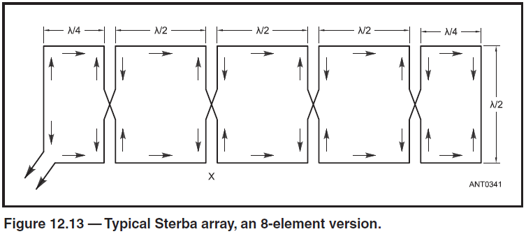
BV205CA.YWChapter 12
Sterba Curtain
Figure 12.13 was omitted from the 23rd edition. The missing figure can be downloaded as a graphic file here.
Chapter 15
Table 15.20
Director 8 (DIR8) should be placed at 1.814 meters from the REF position, not 1.314.
Figure 15.44A
The feed point attachment hardware is more conveniently assembled with the screw heads on the bottom of the driven element instead of on the top as shown. The coaxial feed line is attached to the halves of the driven element and no connection is made to the boom or other hardware.
Chapter 16
A New Spin on the Big Wheel (Cebik and Cerreto) - the article on the CD-ROM should be replaced by its QST In-Depth version (download the ZIP file here) that includes additional material.
Chapter 23
Line Voltages and Currents
Tomi, OH2ID, noticed that equation 18 (page 23-13) and Figure 23.15 (page 23-14) indicate line voltage will increase without limit as the square root of SWR increases. This can be confusing because several sources give Vmax (peak) as equal to (1 + |ρ|) times the square root of 2 times the input power, P, multiplied by the line's characteristic impedance, Zo. (For SWR of infinity, |ρ| = 1.)
The Antenna Book equation assumes that P is the net input power, which on a directional wattmeter equals Pfwd - Prefl, and that none of the reflected power is absorbed by the source (such as a transmitter's output stage). In such a case, power is continually "pumped" into the line. If the termination is infinite, such as for a short or open, power is only dissipated by line loss and voltage can become very high. If reflected power is absorbed by the source, no "build up" of power occurs.
Chapter 24
Figure 24.45 should be shifted down a little so the current labels can be more clearly seen: I1 on the left and I2 on the right. The equation for current should read I2 = 1/2 I1.


